The 3 phase changeover switch operates as the main component which enables systems to switch between different power sources without any interruptions to their electricity supply. The automatic and manual changeover switches provide vital power management functions which operators need to use when they work through different scenarios that apply to industrial sites and commercial buildings and residential areas. This article provides an in-depth examination of the technical operation of these switches together with their benefits and the specific situations where each type of switch operates most effectively. The session will teach you how to choose the appropriate solution which will help your power distribution system achieve maximum operational reliability and efficiency.
Introduction to 3 Phase Changeover Switches
The 3-phase changeover switch functions as a device which enables electrical systems that operate on three-phase power to switch their power supply from one source to another. The system provides uninterrupted power supply through its ability to switch between main power sources and backup generators during power outages. The switches function as essential equipment which industrial facilities and commercial businesses use to maintain their vital operations. The equipment exists in two main categories which include manual and automatic systems because each type serves distinct operational functions. The manual system requires operators to switch power between sources while the automatic system handles power changes by itself to maintain uninterrupted service. The selection process for an appropriate switch depends on evaluation of three elements which include system complexity and needed response speed and financial limitations.
The Importance of Changeover Switches in Power Supply
The essential function of changeover switches as primary elements establishes their role in maintaining power supply systems because those systems need continuous operation during times when power interruptions lead to expensive or dangerous situations. The primary purpose of the system enables operators to switch between different electrical power systems which include main power grid and backup generator systems. The importance of the system can be understood through examination of its main features and advantages which demonstrate its worth for residential and industrial use. The following list presents five major benefits that come from implementing changeover switches in electrical systems.
Uninterrupted Power Supply
Automatic changeover switches provide the ability to switch between different power sources without any interruptions. Automatic transfer switches enable critical systems in hospitals and data centers to switch to backup power sources within milliseconds which prevents both downtime and system failures.
Enhanced Operational Safety
The switches create safe operation conditions by stopping power flow to the system during transfer operation which protects against short circuit and overloading situations. The design protects users from accidents while achieving full compliance with electrical safety regulations.
Versatility and Adaptability
Changeover switches function with multiple power system types which include both three-phase and single-phase power configurations. The equipment functions effectively in home environments and in high-demand industrial settings.
Energy Efficiency and Cost Management
Changeover switches permit users to operate power backup systems which include generator equipment and renewable energy sources like solar panels which leads to better energy management and decreased main utility power expenses.
Durability and Longevity
High-quality changeover switches are designed to endure extreme operational demands which makes them an essential solution for power management needs in difficult working conditions.
The implementation of changeover switches within power systems enables users to create sustainable energy solutions which provide both security and economical benefits.
Overview of 3 Phase Systems
The 3-phase electrical system functions as an effective power distribution method which industrial and commercial and large residential spaces commonly use. The system operates with three alternating currents that share the same frequency and voltage level while their phase angles are separated by 120-degree intervals. The 3-phase configuration delivers significant technical and operational advantages over single-phase systems.
Key Characteristics of 3-Phase Systems
Efficiency in Power Transmission
The 3-phase system creates less energy losses through its power flow because it operates with constant power distribution. Studies show that the 3-phase system requires 50% less conductor material than the comparable single-phase system to transmit power which makes it an economical choice for electricity distribution.
Power Stability
The phased currents maintain a more stable power delivery with minimal pulsation. This stable output is essential for operating sensitive equipment such as motors CNC machines and other industrial tools. The operation of 3-phase motors achieves smoother performance which results in higher energy efficiency and decreased equipment wear throughout their operational lifespan.
Higher Power Capacity
A 3-phase system delivers greater power for the same voltage level compared to single-phase. The 3-phase system provides 415V power to support high-load machinery while single-phase systems maximum capacity reaches only 240V.
Versatility
3-phase systems enable simultaneous operation of single-phase and 3-phase loads which provides users adaptable power solutions. Residential customers typically use both single-phase appliances for their lighting and electronics needs and 3-phase equipment to power their heavy-duty operations.
Data-Backed Advantages
Cost-Effectiveness
The research findings show that 3-phase distribution systems help to lower installation expenses by 25% to 30% when they are used in large-scale projects because they require fewer conductors and transmit power in a more efficient manner than single-phase systems.
Performance Metrics
The research demonstrates that 3-phase motors which operate at identical power levels to single-phase motors achieve 10% to 15% better performance because they use less energy over time.
Applications
The following industrial systems use 3-phase power:
Industrial plants with high-capacity machinery like conveyor belts and compressors.
Commercial buildings requiring robust HVAC systems and escalators.
Data centers which need constant power supply to their servers and cooling equipment.
The implementation of 3-phase power system principles enables users to achieve maximum energy efficiency while minimizing expenses and ensuring their equipment functions with complete dependability. The design demonstrates superior adaptability and efficiency which makes it the leading solution for contemporary electrical engineering and energy distribution systems.
Applications in Residential and Industrial Settings
Residential Energy Solutions
Large residential properties which need to function multiple electrical devices at once require three-phase power systems for their energy needs. Three-phase distribution systems deliver stable efficient power supply which supports central air conditioning units and electric vehicle charging stations that operate at high power requirements.
Industrial Manufacturing Plants
Three-phase power systems serve as the essential energy source which manufacturing plants use to operate their heavy machinery including lathes milling machines and welding equipment. The systems deliver constant power supply which helps industrial facilities maintain their operational standards through precise equipment control and continuous work processes while maintaining their production levels.
Agricultural Operations
Farm operations and agricultural facilities use three-phase systems to power their irrigation pumps grain dryers and conveyor systems. The system maintains stable performance and operational efficiency in areas where power requirements change throughout different times of the year because of seasonal patterns.
Transportation and Infrastructure
Three-phase power systems operate railway electrification and airport ground service systems. The three-phase network establishes a dependable power system which supports electric locomotives and transit systems to operate safely and efficiently.
Commercial Kitchen and Hospitality Equipment
Restaurants hotels and large commercial kitchens use three-phase systems to operate their high-capacity equipment including industrial refrigerators and dishwashers and specialized electrical ovens. The system enables this industry to handle heavyweight operations because it maintains complete performance through its entire operational capacity.
Technical Specifications of 3 Phase Changeover Switches
Three-phase changeover switches serve as essential elements for electrical systems because they provide two essential functions which include maintaining continuous power supply and enabling effective load control during power source changes. The following section presents a comprehensive description of their primary engineering specifications:
1. Voltage Rating
Three-phase changeover switches operate within the voltage range of 380V to 690V AC which defines their standard operational parameters. The specific ratings of the system depend on the needs of the application because it must work in both industrial and commercial settings. The common models operate efficiently with standard three-phase voltage systems because they maintain complete power efficiency.
2. Current Capacity
The switches can handle electrical loads between 16A and 3200A which makes them appropriate for different power requirements. High current-rated units operate in large facilities such as data centers and manufacturing plants while lower-rated variants serve smaller facilities.
3. Switching Mechanism
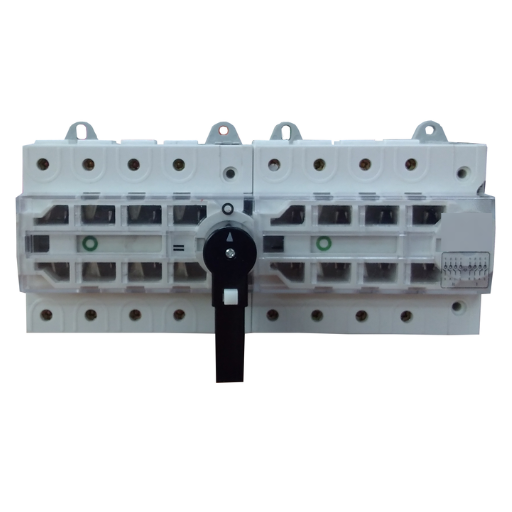
Modern three-phase changeover switches operate through three advanced control methods which include manual operation and automatic operation and motorized control to enable power switching between mains electricity and backup generators. The automatic transfer switch system should be used in critical applications because it allows for immediate power transfer during outages which reduces system downtime.
4. Pole Configuration
These switches offer three-pole and four-pole options which use their fourth pole specifically for grounding neutral connections. The system design achieves load balancing between different components while improving system protection.
5. Breaking Capacity The rated breaking capacity demonstrates how well systems can manage short circuit conditions because high quality switches need to exceed 6kA capacity. The system maintains strong functionality throughout operational environments that experience frequent faults.
6. Durability and Lifespan These devices maintain their operational capacity for more than 10000 mechanical operations and 5000 electrical cycles because manufacturers designed them to last for extended periods. The housing materials use flame retardant and moisture resistant properties to safeguard the internal components from damage.
7. Protection Class Three-phase changeover switches receive protection classes IP54 and IP65 and IP67 which protect the devices from dust and moisture and water penetration. The system functions effectively for both indoor spaces and outdoor environments.
8. Operating Temperature Range The system maintains operational efficiency between -25°C and +70°C which enables it to function reliably in extremely cold and high-temperature settings.
9. Compliance and Standards High-quality switches comply with international standards such as IEC 60947-6-1 which establishes transfer switching equipment requirements and ISO 9001 standards for quality assurance to guarantee safe operation across different installations.
10. Monitoring and Indicators Most modern models include LED indicators and digital displays and remote monitoring capabilities which provide enhanced system control and enable real-time diagnostics that assist with system maintenance and fault detection. The technical sophistication of three-phase changeover switches combines with their strong construction to create dependable systems that power essential operations in industrial and commercial and infrastructure environments.
Understanding the Components: Contactors and Relays
The contactors and relays serve as essential elements which support electrical systems throughout control circuits and automated systems and three-phase power distribution systems. The two devices possess similar physical structures yet their operational capabilities and usage scenarios depend on the specific requirements of different electrical systems.
Contactors function as electrical switches which power circuits through their ability to control high-current electrical loads. The device contains contacts which operate continuously in industrial settings to support motor and transformer and heavy machinery operations. The current rating of modern contactors exceeds 100 Amps according to IEC and ANSI standards, while their voltage rating extends up to 1000 Volts AC. The equipment includes arc suppression systems which operate through magnetic blowout and arc chute technologies to endure extreme load situations.
Relays are compact devices that function as control elements for low-power electronic circuits. The devices act as control elements which enable circuit isolation and high-current device activation through their design which requires minimal input current. Typical relays have contact ratings ranging from milliamperes to around 15 Amps, with voltages generally below 250 Volts. Solid-state advanced relays provide silent operations with faster switching times because they use no mechanical components.
The three-phase motor control circuit operates through specific functions. The contactor directly switches the motor’s high-power circuit, while relays handle auxiliary functions like signal processing or fault detection. Siemens, Schneider Electric, and ABB develop new products through their research which adds protection against overloads while including thermal sensors and remote control features to improve system reliability and automation functions.
Engineers achieve their design goals in power systems by studying how relays and contactors function because these systems need to operate efficiently while remaining dependable across different operating conditions.
Types of Phase Changeover Switches: Manual vs. Automatic
Electrical systems depend on phase changeover switches to maintain continuous power distribution through their ability to switch between multiple power sources which include mains power and generator systems. The operation of these switches can be divided into two main categories which consist of manual switches and automatic switches. The two switch types provide distinct benefits which match different operational requirements and specific situations of use.
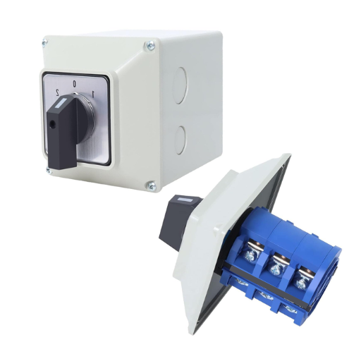
Manual Phase Changeover Switches
Manual phase changeover switches require human intervention to switch between power sources. The process involves physically toggling a lever or switch to shift from one source to another. These switches are typically used in smaller installations where automation is not necessary or when there is a need for direct user control.
Key Features:
- Cost-effective: Lower initial investment compared to automatic switches.
- Simple Design: Minimal moving parts reduce the likelihood of mechanical failure.
- Applications: Commonly used in residential buildings and small-scale commercial setups.
Examples of Manual Phase Changeover Switches:
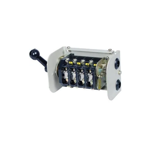
- Handle-operated rotary changeover switch.
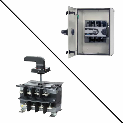
- Knife-blade manual transfer switch.
- Cam-operated manual changeover switch.
- Push-button manual changeover unit.
- Toggle-operated manual changeover system.
- Automatic Phase Changeover Switches
Automatic phase changeover switches operate without human intervention, ensuring a seamless transition between power sources. The control circuits with their sensors system automatically switches to backup power when they detect power outages or voltage anomalies. The switch automatically switches back to its primary power source when normal power supply resumes operation.
Key Features:
The system achieves power transfer without interruption, which protects critical operations from downtime and service disruptions.
The system provides remote access together with its programmable control features.
The system finds application across various industries including hospitals and data centers which require high operational reliability.
Examples of Automatic Phase Changeover Switches:
- Microprocessor-controlled automatic transfer switch
- Motorized rotary automatic changeover switch
- PLC-integrated automatic switch with monitoring features
- Smart automatic transfer switch with IoT support
- Zero-lag automatic hybrid transfer switch
The selection between manual and automatic phase changeover switches depends on three main factors, which include budget constraints and the importance of the application and the needed automation level. The right selection process enables both system performance optimization and power management effectiveness.
Key Ratings: Amperage and Voltage Specifications
The selection of a phase changeover switch requires understanding its amperage and voltage specifications which ensures system compatibility and operational reliability for electrical systems. The switch operates at amperage which defines its current-carrying capacity while the voltage specification shows the maximum voltage the device can handle without danger of failure.
Amperage Ratings:
Residential phase changeover switches typically range between 63A and 125A which delivers enough power to meet common household requirements.
Commercial and industrial applications require switches with ratings between 160A and 630A to meet their higher electrical power requirements.
High-capacity systems designed for heavy-duty applications, such as data centers or manufacturing facilities, can exceed 1000A because they need to maintain continuous power delivery during extreme operational situations.
Voltage Ratings:
The standard operating voltage for low-voltage systems which residential and light commercial areas use operates at 230V for single-phase and 400V for three-phase systems across most regions.
Medium-voltage switches, with ratings from 1kV to 35kV, are generally used in larger commercial and industrial facilities.
High-voltage scenarios, such as utility-scale applications, may require switches rated over 35kV, depending on grid specifications.
Additional Considerations:
Safety Margins:
The switch should have both voltage and amperage ratings which exceed the maximum expected load by 20 to 25 percent for safe operation without risking overload.
Frequency Compatibility:
Switches operate at standard frequencies which most devices use because their electrical systems follow either 50 Hz or 60 Hz regional standards.
Short-Circuit Ratings:
High-performance switches include short-circuit withstand ratings which engineers express in kiloamperes (kA) to show their fault condition handling capacity.
Operating Temperature:
The switch must receive operational temperature rating for the environment which operates between -10°C and 55°C while industrial-grade switches provide temperature ratings that extend beyond this standard range.
The technical parameters will direct the selection process because they help determine which phase changeover switch meets your application requirements while providing optimal safety and efficiency.
Common Applications for Automatic Changeover Switches
Automatic changeover switches are used in applications that need permanent power supply. These devices enable power source switching which helps systems operate continuously without interruptions. The section presents five typical uses together with their specifications and the necessary factors to consider.
Hospitals and Healthcare Facilities
Automatic changeover switches function as essential components in hospitals because they guarantee continuous power supply for medical equipment and life-support systems and vital hospital functions. Surgical procedures and ICU monitoring systems require instant power switchovers from primary to backup sources because any delays would cause dangerous consequences. Equipment failures in these environments result in hourly downtimes that generate equipment downtime costs which reach thousands of dollars.
Data Centers
Data centers need to experience only minimal power interruptions because such events would endanger server protection and stop data from being available. The system uses automatic changeover switches to connect utility power with backup generators which protects data from being lost or damaged. The industry reports show that a single power outage in a data center will cost between $100,000 and $500,000 which makes these switches essential for operation.
Commercial and Industrial Manufacturing
Most manufacturing plants operate their automated machinery systems which need continuous power supply for proper functioning. The installation of changeover switches enables operational facilities to maintain machinery operation through power outages which helps maintain production and protect valuable equipment. The manufacturing sector study shows that production operations lose an average of $260000 per hour because of power interruptions that last only a few minutes.
Telecommunication Towers
The telecommunication infrastructure needs automatic changeover switches because remote towers require these switches to switch between grid power and battery or generator backup systems. The switches maintain network service continuity which enables nonstop communication. The system becomes essential for emergency situations because it needs to maintain network services without interruption.
Residential Complexes and High-Rise Buildings Apartment complexes and high-rise buildings use automatic changeover switches to ensure their elevators and lighting systems and essential services receive nonstop power supply. The system enables automatic power supply management which benefits residents by providing both operational convenience and safety. Statistics indicate that integrating changeover solutions in residential settings significantly reduces tenant complaints related to power failure scenarios.
The various industries use automatic changeover switches to achieve two purposes because they need operational stability and safety during sensitive power operations.
Usage in Generator Systems
Automatic changeover switches function as essential components within generator systems because they enable generators to switch power sources without interruption. The system requires these components in order to maintain power supply during both power outages and voltage variations. The following section presents five specific use cases together with corresponding operational data which demonstrates their effectiveness in generator systems.
Backup Power Activation
Automatic changeover switches serve as the standard method to start backup generators which protect systems during primary power outages. Research shows that these systems can achieve operational continuity for hospitals and data centers because they need less than 0.5 seconds to respond to emergencies.
Load Balancing
The system functions to distribute power demands between generators and primary utility power lines for maximum efficiency. The function serves industrial operations because unbalanced power distribution results in equipment overheating which leads to operational disruptions that can boost costs by 15% when implemented.
Overload Protection
The switches monitor power usage to prevent generator overloads by transferring extra demand to different power sources. Data shows that generators equipped with proper overload protection systems can extend their operational lifespan by 20 to 30 percent.
Integration with Renewable Energy Systems
The system uses automatic changeover switches for all renewable energy systems which include solar power and wind power. The system maintains electrical power through generator activation during times when renewable energy production falls short, achieving 98 percent dependable operation in hybrid energy systems.
Remote Monitoring and Control
The modern automatic changeover switch system includes IoT capabilities which enable users to monitor and control generator operations from a central system. The system minimizes the need for physical work while it achieves 25 percent reduction of maintenance expenses at large industrial sites.
The functions of automatic changeover switches in generator systems demonstrate their vital importance, which lets these systems maintain operational security for emergency power requirements.
Implementing ATS for Seamless Power Transfer
The operation of Automatic Transfer Switches (ATS) systems functions as a vital component that supports continuous power delivery throughout residential and industrial environments. The ATS systems detect power outages and voltage fluctuations through their automatic detection system which switches power supply to backup generators. The system enables quick changes because its advanced technology can complete transfers within 10 to 20 milliseconds which keeps essential operations running without interruptions at data centers and hospitals and manufacturing facilities.
Modern ATS solutions use microprocessor controllers which enable real-time voltage and frequency and phase synchronization monitoring through their advanced technological features. The use of ATS systems in facilities results in 40 percent improved power reliability during outages according to research studies. The combination of ATS with Internet of Things (IoT) systems and predictive analytics results in better operational efficiency through automated diagnostics which detect potential problems at an early stage.
The load prioritization feature of ATS systems plays an essential role in supporting industrial organizations with their power distribution needs. High-capacity ATS systems enable operation with loads that reach 4,000 amperes while they also provide load shedding capabilities which help critical systems continue working within generator power limitations. Energy-intensive industries like data centers and telecommunications need ATS systems which meet Tier IV reliability standards that require 99.995 percent uptime.
ATS installations achieve safety and durability through their compliance with UL 1008 standards which serve as transfer switch regulations in North America. The standards establish that the switch can manage inrush currents while protecting against electrical arcing which guarantees smooth and safe power transfer operations. The advanced capabilities which ATS systems provide serve as power protection systems that work to secure essential electrical infrastructure.
Backup Power Solutions with 3 Phase Changeover Switches
Three-phase changeover switches ensure that critical operations receive continuous power supply. The design of these switches enables automatic switching between main electrical supply and backup generator systems which prevents power outages in commercial and industrial and residential settings. The systems deliver dependable performance which creates essential value for building secure electrical systems. The following list presents five essential specifications which describe the three-phase changeover switches used in current backup power systems.
High Current Capacity
The system supports current flow between 63A and 1600A which enables operation with diverse electrical load requirements.
Automatic and Manual Switching Options
The system provides automatic transfer functionality which enables instant power supply changes during power outages together with manual control options to give users more operational power.
Durable Construction
The system uses high-quality materials which include flame-retardant plastics and corrosion-resistant metals to achieve long-lasting operation in extreme working conditions.
Wide Voltage Range Support
The system operates effectively between 220V and 690V which makes it applicable for different operational requirements.
Compliance with International Standards
The system meets International Electrotechnical Commission standard IEC 60947-6-1 which ensures safe and dependable performance under challenging electrical conditions.
The 3 phase changeover switches provide dependable backup power solutions which improve system resilience and operational effectiveness across different industries.
Safety Considerations for 3 Phase Changeover Switches
The implementation of three-phase changeover switches needs strict safety protocol adherence which delivers dependable performance while safeguarding against system failures and dangerous situations. The following five safety requirements represent essential safety requirements:
Proper Installation and Wiring
The installation of the switch needs qualified personnel who will execute the work according to manufacturer instructions. The system will experience integrity problems because incorrect wiring will create short circuits and phase imbalances.
Cables should use correct sizes which will enable them to handle the load current while reducing the chances of overheating.
Load Capacity Matching
The switch must have a capacity that meets or exceeds the maximum load requirements. An under-rated switch will cause equipment damage through overheating which creates fire hazards.
Periodic Maintenance and Inspection
The team needs to perform regular inspections and maintenance work to find problems which include loose connections and corrosion and wear in the switch mechanism. The switch operational life span increases through regular maintenance which also decreases the chances of equipment breakdowns.
Overcurrent and Overvoltage Protection
The system requires overcurrent protection through circuit breakers and fuses which act as protective devices. The system needs surge protection mechanisms which will stop damage from voltage spikes.
Compliance with Safety Standards
The switch must meet all applicable international standards including IEC 60947-6-1. The device meets basic safety requirements through standard compliance which also establishes performance and reliability assessment standards.
The safe operation of three-phase changeover switches depends on operators from these safety requirements which, when followed, will improve switch performance.
Adhering to Safety Standards and Regulations
All 3-phase changeover switches need installation and operation and maintenance processes that meet safety standards and regulations. The following list contains five essential safety standards and regulations which require mandatory compliance:
IEC 60947-6-1
The standard establishes requirements which apply to low-voltage switchgear and controlgear while specifically assessing switch performance and operational durability and safety requirements during changeovers. The document establishes performance standards which include electrical endurance testing and thermal stability assessment and insulation testing.
IEC 61439
This standard applies to low-voltage switchgear and controlgear assemblies. The standard helps create secure and strong and dependable switch enclosures with their related components through its compliance requirements.
NFPA 70 (National Electrical Code – NEC)
The code establishes guidelines for safe electrical design practices that apply to installations throughout the United States. The code establishes procedures which protect against electrical hazards including shock events and fire incidents and arc flash occurrences.
EN 60204-1
The standard protects electrical equipment present in machinery through its established safety requirements. The standard provides operational guidelines which include short circuit protection and proper grounding methods and assessment of equipment performance in actual environmental conditions.
ISO 45001
The standard establishes requirements for systems that manage workplace health and safety. The standard helps organizations protect worker safety through its requirements which govern implementation and maintenance of systems such as changeover switches.
The standards require implementation to achieve maximum equipment efficiency and lifetime protection which secures both equipment operators and facility operations from dangerous situations. The compliance requirements for 3-phase changeover switches depend on the vital function which each standard performs within the system.
Best Practices for Installation and Maintenance
To operate the 3-phase changeover switches safely and efficiently, organizations must implement established best practices during their installation and maintenance procedures. The following key practices receive support through specific recommendations and documented evidence.
Proper Load Analysis
Before installation, conduct a thorough load analysis to determine the maximum load capacity the changeover switch will need to handle. The switch must receive a safety rating that exceeds 125% of its anticipated load because this protects against sudden power increases which might cause equipment breakdowns. The switch needs to have a minimum rating of 150A when it operates with a 120A system.
Use of Manufacturer-Approved Components
The organization must use only manufacturer-approved components which include fuses and connections. The approach guarantees component compatibility, which diminishes the chances of components failing prematurely or functioning at reduced efficiency or losing their warranty protection.
Regular Inspection and Cleaning
The switch needs inspection at least every three months to check for damage and corrosion and dust buildup. Equipment that receives poor maintenance shows a failure rate which exceeds equipment that undergoes regular maintenance by 40%. Approved solutions should be used to clean electrical contacts because they help maintain contact conductivity.
Tightening of Connections
Loose connections create a risk of arcing which leads to complete equipment breakdown. The maintenance procedure requires technicians to inspect all terminal screws and connection points while applying the manual torque specifications which range between 40 and 50 Nm for industrial-grade switches.
Testing Backup Systems
The maintenance checks must include tests which evaluate the backup power supply system. The team needs to create a simulated power outage which tests whether the changeover switch can transition between power sources without delays or system failures. The testing process requires documentation because it helps track performance patterns and identifies upcoming challenges.
The implementation of these best practices increases the operational life of 3-phase changeover switches while simultaneously decreasing operational interruptions which results in a dependable power management system.
Identifying Common Risks and Troubleshooting
The management process for 3-phase changeover switches requires operators to identify potential hazards before they occur and establish troubleshooting methods which ensure system reliability. The following section presents five typical hazards which include their specific causes and their respective solutions.
Contact Wear and Degradation
Details: The switch operation creates repeated electrical arcs which result in contact wear because the contact points become worn out. The system becomes unsafe and performs badly after this process continues for an extended period.
Troubleshooting: The switch contacts need inspection to detect pitting and discoloration and excessive wear. The cleaning process involves using proper tools to clean the contacts while any worn parts need replacement once their wear reaches the manufacturer-defined limits.
Mechanical Malfunctions
Details: The system operation experiences disruptions because of mechanical failures which include switching mechanism misalignment and actuator component wear. These problems occur when systems undergo extended operations without receiving proper lubrication.
Troubleshooting: The maintenance schedule needs to include tests which verify system alignment and lubrication status. The system requires mechanical component adjustments or replacements according to the equipment operating manual.
Overheating Due to Overloads
Details: Switch overheating occurs when excessive current flows through the switch which results in thermal damage and insulation breakdown. The constant overload condition leads to more contact damage.
Troubleshooting: The system uses thermal imaging technology to locate high-temperature areas which occur during operation while the system needs to maintain balanced electricity distribution between different parts. The organization needs to implement circuit protection devices including fuses and thermal relays to protect against overload situations.
Improper Installation or Configuration
Details: The switch operational capabilities and protective mechanisms get affected by incorrect wiring and improper phase alignment and missing installation protocol requirements. The risk exists because system setup needs to begin with the first deployment of equipment.
Troubleshooting: Proper installation requirements need to be checked through both the installation manuals and the wiring diagrams. The system needs to go through complete commissioning tests which will validate its setup before it starts operating.
Environmental Factors
Details: The switch components face performance deterioration because they come into contact with dust and moisture and extreme temperature conditions and corrosive materials.
Troubleshooting: The switch needs protection from environmental factors through the use of enclosures which have suitable IP protection levels. The team needs to conduct environmental assessments at regular intervals while maintaining sufficient airflow to stop internal moisture accumulation and equipment overheating.
The operational reliability and efficiency of 3-phase changeover switch systems improve through the prevention of common risks which requires regular maintenance and active problem resolution. The process of regular diagnostic testing and performance evaluation will enable the team to detect new issues as they arise.
Installation and Maintenance of 3 Phase Changeover Switches
The efficient operation of a 3-phase changeover switch depends on its proper installation which also establishes safe working conditions. The following installation procedures explain industry best practices together with current technological standards.
Pre-Installation Preparations:
The switch voltage and current ratings must be verified to match the requirements of the electrical system. A 400V switch functions as a standard equipment for commercial and industrial applications.
The technician must examine the switch to identify any existing physical damage or operational defects before starting the installation process.
The team must obtain all necessary tools which include insulated gloves and multimeters as well as torque wrenches.
Mounting the Changeover Switch:
The selected installation location must provide enough area for operators to conduct their duties while maintaining equipment and allowing heat to escape.
The switch must be securely mounted to a wall or panel through the use of proper anchoring methods which require the installer to follow specific mounting instructions while connecting components.
Electrical Connections:
Workers must establish power supply isolation before they start electrical operations on the circuit.
The input terminals must be connected to primary and secondary power sources according to the manufacturer’s instructions which include both utility grid and backup generator power connections.
Technicians need to implement load-side wiring routes which prevent any possibility of cross-phase contact while they must secure all connections to decrease resistance and protect against overheating.
Testing and Commissioning:
The technician needs to conduct continuity tests which will establish whether the system functions correctly through its wiring and polarity connections.
The team will energize the system under controlled conditions to test whether the switch performs its function of transferring power between sources during simulated outages or load shifts.
The testing standards which apply to low-voltage switchgear must follow IEC 60947 standards.
Maintenance Best Practices
Regular maintenance work is necessary to achieve lasting dependability for 3-phase changeover switches. The current industry reports indicate that maintenance neglect causes up to 20% of switch failures. The following guidelines serve to reduce these risks.
Visual Inspections:
The switch needs regular inspection to detect any signs of wear or corrosion or overheating which occurs at contact points.
The terminals need testing to find any loose parts while damaged insulation needs detection to stop short circuits or arcing.
Cleaning Procedures:
The cleaning process needs non-conductive cleaning agents for dust and dirt and oxidation removal from components.
The cleaning process requires control of moisture levels because excessive moisture will damage electrical components.
Lubrication:
The correct lubricants need application to all mechanical parts which include handles and toggle mechanisms for ongoing operational efficiency. The person needs to handle equipment with electrical parts while avoiding direct contact with electrical parts.
Testing and Calibration:
The switch needs testing to measure transfer time and load capacity every six months because these results need to stay within established limits.
The process requires diagnostic tools which include thermal imaging cameras to find hotspots and track insulation condition through time.
Upgrades and Replacements:
The company should adopt modern technology by implementing switches which contain monitoring capabilities that will notify operators about faults at all times.
The company needs to replace components which have reached their designated lifecycle or based on the manufacturer specifications to maintain efficient operations.
Common Installation and Maintenance Challenges
Several challenges may arise during the installation and maintenance of 3-phase changeover switches. The following challenges exist:
Voltage Fluctuations:
Switch components experience degradation because incoming power supply fluctuations create persistent voltage changes. The installation of surge suppressors is recommended to safeguard against this issue.
Environmental Factors:
Operating switches in environments with extreme temperatures, humidity, or dust may lead to accelerated component deterioration. Enclosures that have an IP65 rating or higher can protect the switch from all external elements.
Operator Error:
Installation errors caused by incorrect wiring or improper handling lead to system failures which prevent power transfer operation. Training personnel on precise installation techniques and maintenance schedules can mitigate such risks.
The installation and maintenance protocols should be followed to improve 3-phase changeover switches operational capacity and safety and equipment lifespan. Industrial and commercial applications require proper handling of these crucial systems which provide continuous power supply.
Step-by-Step Installation Guide
Pre-Installation Preparation
The 3-phase changeover switch specifications must be verified to determine their suitability for the site’s voltage and current requirements. The available models for this device range from 63A to 1600A which enables industrial operations across different power needs. The system requires complete inspection because all components must be checked for visible damage that occurred during transit. The presence of damaged parts results in unsafe conditions which make it impossible to operate the system.
The installation process requires you to obtain all essential equipment which includes torque wrenches and screwdrivers and multimeters and protective gear which meets safety standards.
The system requires complete power disconnection because all sources need to be disabled which will protect against electrical shock hazards during switch installation.
Mount the Switch
The switch requires installation in a location which provides both security and stability. The installation requires mounting on a vertical surface which does not catch fire and stays away from areas with intense vibrations.
The switch needs proper spacing to enable both ventilation needs and upcoming maintenance tasks. The industry guidelines recommend maintaining at least 4 inches (10 cm) clearance throughout all sides of the area.
The installer must use bolts or brackets to secure the switch which requires exact alignment for proper installation without causing damage to the casing.
Connection of Input and Output Terminals
Input Terminals: The power supply lines (L1, L2, L3) need to be connected from the main power source to the particular input terminals which the switch designates. The terminals come with identification labels which make them easy to find.
Output Terminals: The load-side wires should be connected to the output terminals which will establish the correct connections according to the phase sequence requirements. Equipment will sustain damage because improper phasing creates operational issues.
The terminal screws must be tightened with a torque wrench which requires the operator to use the torque value specified by the manufacturer in the datasheet which usually ranges from 4.5 to 10 Nm for mid-range switches. The system prevents connections from becoming loose which creates a risk of overheating and arcing.
Grounding
The switch requires its grounding terminal to connect with the facility grounding system through a correctly sized cable which needs to meet AWG 6 minimum requirements for large systems. The grounding system requires testing with an earth resistance tester to verify its continuous operation. Standard resistance values typically must not exceed 1 ohm. This step is crucial for ensuring user safety and meeting regulatory requirements.
Testing and Commissioning
The power source needs to be reestablished before we can test the switch in a controlled environment. The testing process requires operational testing with both normal power and backup source power while simulating load conditions to verify power transition efficiency.
The multimeter verifies voltage levels at all terminals which ensures proper power distribution without any voltage changes. Voltage imbalances should not exceed 2% according to IEEE guidelines.
The system overload protection needs verification through protective relay configuration which should follow the established design specifications.
Post-Installation Checklist
The inspection needs to check all connections for security while searching for visible wires or loose parts that should not be present. The installation details need documentation which includes the switch model and configuration settings as well as the test results for future maintenance purposes.
Operational personnel require training on the procedures for safe operation and maintenance of the changeover switch.
The 3-phase changeover switch requires you to follow these specific steps because they will guarantee its reliable operation during extreme conditions which will protect essential power systems from downtime.
Regular Maintenance Tips to Ensure Longevity
The operational life and efficiency of a 3-phase changeover switch requires its regular maintenance to function at optimal levels. The following five maintenance procedures present detailed explanations which support their execution with data-based evidence.
Visual Inspection
The switch housing terminals and connections should be checked through visual inspection which must be conducted every month to confirm their condition. Studies show that visual inspections reduce the likelihood of unexpected failures by up to 30%.
Clean Contact Surfaces
The contact points need inspection and cleaning twice a year because oxidation and carbon deposits build up which disrupts electrical conductivity. The best results can be achieved through using a soft brush together with the contact cleaner which equipment manufacturers recommend.
Torque Check on Connections
All terminal connections need to be checked with a calibrated torque wrench every year to verify their compliance with the manufacturer’s torque requirements. Loose connections create overheating risks while tight connections cause component damage which results in 20% higher failure rates.
Lubricate Mechanical Components
The organization needs to apply suitable lubricants to all moving components including levers and switch mechanisms after every six-month period. Proper lubrication eliminates friction and wear which would otherwise increase failure risk by up to 15%.
Test Switch Functionality Under Load
The changeover mechanism functional test needs to be executed every six months under controlled load conditions to verify its ability to switch between power sources. The system should record transition times and any abnormal noises or hesitations to assist in monitoring system performance and identifying emerging problems.
Common Issues and How to Resolve Them
Power Source Transfer Delay Problem
The transfer switches experience a transfer delay which exceeds the time limits that manufacturers established for their power source transitions. This increases the possibility of power outages which affect essential systems.
The problem occurs because maintenance has not been done properly and the actuators have broken down and the contact points have worn out.
The solution requires contact point inspection and cleaning every six months while worn actuators need replacement. The team will perform transition time tests with regular intervals to gather data which will help them assess performance.
Excessive Wear on Moving Components
The switch needs to operate frequently because its operations lead to mechanical damage which makes certain parts unresponsive and results in improper component alignment.
The problem occurs because systems lack proper lubrication and materials experience fatigue and operations run beyond their recommended capacity.
The organization must create a lubrication plan which uses manufacturer-approved lubricants to service all of its moving components. The organization needs to examine parts every three to six months to determine their fatigue status and replace components as necessary.
Voltage Spikes During Transfer
Voltage irregularities transmit through power transfer operations because voltage spikes and voltage sags produce equipment damage at downstream systems.
The transfer switch control circuits have developed a fault and the timing settings have been incorrectly set.
The solution requires calibration of timing settings which will reduce transfer gaps and operational testing of voltage levels. The organization will replace or fix control circuits when they identify any operational abnormalities.
Overheating of Electrical Contacts
When contacts experience prolonged heating or excessive heating which exceeds a threshold contact resistance increases and efficiency drops and contact failure becomes likely.
The problem occurs because contact surfaces become contaminated through corrosion and dirt accumulation and contact tension has been set incorrectly.
The organization will conduct thermal imaging inspections every three months to locate overheating areas. The organization needs to clean contacts using proper solutions while adjusting contact tension according to the manufacturer guidelines.
Power Source Synchronization Failure Problem
The transfer switch encounters power transfer issues because it cannot synchronize both frequency and phase between power sources.
The system experiences failures because the synchronization circuits either malfunction or they need periodic calibration.
The organization needs to perform annual synchronization testing through dedicated equipment testing to validate their synchronization systems.
The team needs to re-calibrate synchronization settings according to operational standards while they should replace all defective circuit components without delay.
References
- Smart Phase Change-over System with AT89C52 Microcontroller
Read the paper on Academia.edu - Design and Construction of an Automatic Power Changeover Switch
Read the paper on Academia.edu - Automatic Phase Changer: A Review
Read the paper on Academia.edu
Frequently Asked Questions (FAQ)
What is a three phase changeover switch and how does it work?
The three phase changeover switch functions as a mechanism that allows electrical equipment to switch between its main power supply and its emergency power source which can be a backup generator or inverter. The system functions specifically for three-phase power systems whereas users have the option to operate it through manual controls or automatic operations. The switching system functions by transferring all three electrical phases at once which enables delivery of balanced power distribution to industrial equipment, large HVAC systems, and other vital operations.
When should I use a generator transfer switch versus manual transfer switches?
Use an automatic transfer switch or generator transfer switch when uninterrupted power and fast recovery are required for critical systems or industrial operations; these automatically switch to the backup source with minimal downtime during a power failure. Manual transfer switches function effectively for both noncritical loads and situations that need human control to operate. The selection process needs the evaluation of load requirements, safety requirements which include disconnect and circuit breakers, and the need for remote monitoring or automatic transfer functionalities.
What are the benefits of a 3-phase automatic transfer switch for industrial facilities?
The 3-phase automatic transfer switch guarantees reliable power continuity through its automatic switching mechanism which transfers electrical load to backup generator systems during main power outages. The system protects sensitive equipment because it maintains continuous power supply to essential systems while meeting regulatory power system standards which include IEC 60947-3. Automatic switching systems enable industrial facilities to maintain operational productivity while decreasing the need for workers to perform physical tasks.
Can an inverter be used as a backup source with an automatic transfer switch?
The three-phase changeover system allows inverter or UPS equipment to function as backup power sources. The transfer switch enables load operations between main power and inverter systems which supply continuous power to essential equipment. The system needs to work with inverter output according to switching system and electrical circuit protection elements which include circuit breakers and terminal sizing requirements needed for safe operation.
How does a switch 3 phase maintain uninterrupted power during an outage?
The switch system for three-phase power distribution maintains consistent electricity supply through quick transfer of electrical demands from main power lines to backup electricity systems which include generators and inverters and other power sources. Automatic transfer switches activate backup power systems after they detect power outages while certain systems use UPS systems to provide temporary power until the generator begins operation. The combination of circuit breaker coordination and IEC standard compliance delivers secure power continuity which maintains operation throughout extended periods without interruptions.
100a terminal: How do terminal ratings like 100a or 4p 63a affect selection of a three-phase changeover switch?
The maximum current capacity of the switch system depends on its terminal ratings and ampere capacities which include 100a and 40a 3 and 4p 63a specifications. Select a switch with terminal ratings that match or exceed your maximum load needs to prevent equipment overheating and ensure dependable backup power and to stop circuit breakers from activating. The design of large industrial loads requires oversized terminals and strong building materials to stop short circuits from happening and to maintain operational dependability through time.
What safety and code considerations apply when installing phase manual or manual transfer switches?
You need to follow local electrical codes and IEC 60947-3 standards for both the manual transfer switches and the phase manual installation process. The system requires proper disconnection procedures which need to have all power sources marked as primary and backup. The system needs to work together with circuit breakers. The installation requires NEMA 3R enclosures which need to be installed by trained staff who will perform switching operations to protect both personnel and equipment. The system needs proper grounding together with clear separation between main power and generator power for safe operation.
How do three-phase systems integrate with single phase loads and protection devices?
Three-phase systems provide power to both three-phase and single-phase electrical loads. The integration process needs correct distribution through transformers or tap points together with circuit breakers that match the size requirements of each circuit. Electrical systems experience less stress when balanced load distribution operates across all phases because it stops neutral currents from flowing. The system needs transfer switches and disconnects that match its type together with terminals and protection systems that can safely manage both 3-phase power and single-phase loads.
What environmental and monitoring features should I consider for a three-phase automatic switch in harsh conditions?
For outdoor or harsh environments choose enclosures rated NEMA 3R or higher to protect against rain and debris. Backup power systems require remote monitoring to track system status and fault alarms and conduct automatic transfer diagnostics which will help power outages to be resolved quickly. The system requires verification of IEC standard compliance together with verification of robust terminal and breaker construction and verification of large industrial application suitability which will help to maintain continuous power supply while minimizing operational downtime.