The guide explains the procedure which helps users select appropriate wiring for their 40 amp circuit needs. The article will teach you how different factors determine wire size selection which includes ampacity and wire material and insulation type. The resource enables both skilled DIY enthusiasts and homeowners who seek professional help from electricians to understand how to choose safe and well-informed solutions.
Introduction to 40 Amp Circuits
A 40 amp circuit provides power to high-demand appliances in residential and commercial spaces which include ovens and electric water heaters and large air conditioning units. The circuit needs wiring that can properly manage its electrical capacity because this will prevent both overheating and fire dangers. The National Electrical Code (NEC) specifies that copper wires of at least 8-gauge or aluminum wires of at least 6-gauge are suitable for 40 amp circuits. The factors which should be evaluated to select wire dimensions include wire material and circuit distance. Always ensure the local electrical codes have been followed during wiring installation and contact a licensed electrician for necessary guidance.
The Importance of Correct Wire Size
The safe operation of electrical systems needs proper wire size because wire size determines both safety measures and system performance and operational limits. The use of wrong wire size leads to excessive heat production and voltage loss which creates fire risks. The correct wire size selection requires five essential details which demonstrate its critical role in electrical systems.
- 1
Prevention of Overheating: Undersized wires can overheat because their resistance creates heat which melts insulation and develops fire hazards.
- 2
Voltage Drop: If the wire size is too small, it can cause a significant voltage drop over long distances which results in decreased performance for connected devices and leads to potential equipment damage.
- 3
Ampacity Ratings: Each wire size and material has an ampacity rating which indicates the maximum current it can safely carry without exceeding its temperature rating.
- 4
Material Differences: Copper and aluminum wires have different conductivity properties because copper provides better conductivity and needs smaller gauge sizes than aluminum to achieve the same ampacity.
- 5
Compliance with Electrical Codes: Adhering to local and national electrical codes such as the NEC ensures that wiring installations are safe and meet standard requirements for current loads and environmental conditions.
The correct wire size selection should be based on these factors because it establishes essential requirements for electric system security and reliability maintenance. The best solution for doubt situations requires you to contact professional electricians.
NEC Compliance and Safety Standards
The National Electrical Code (NEC) which exists as NFPA 70 serves as an essential standard which establishes safety requirements and efficiency standards for electrical system installations. The NEC provides complete design and installation and inspection standards which govern electrical systems in residential buildings and commercial spaces and industrial facilities and the code updates its standards every three years. The NEC requirements decrease fire hazards and electric shock risks while electric power usage stays efficient and systems maintain dependable performance.
Key NEC Requirements and Standards
Conductor Ampacity and Sizing
The NEC requires installation teams to use specific minimum conductor sizes which they calculate through ampacity assessment together with temperature rating and insulation type and installation conditions. The most common applications utilize 12 AWG stranded copper conductors which have a 20 ampere rating while aluminum conductors need larger sizes to achieve the same capacity across the same AWG rating.
Grounding and Bonding
Experts state that organizations need to create appropriate grounding and bonding systems which will enable them to perform safe operations while securing their valuable equipment against potential harm. The NEC establishes exact requirements for grounding electrode systems which contain rods and plates and pipes and it specifies the dimensions which bonding jumpers and conductors must have.
Circuit Protection
The NEC Article 240 establishes requirements which determine the correct sizing of overcurrent protection devices that include breakers and fuses. A 15-amp breaker requires 14 AWG conductors as the minimum requirement which establishes the connection between the two elements.
GFCI and AFCI Requirements
Ground Fault Circuit Interrupters (GFCI) and Arc Fault Circuit Interrupters (AFCI) must be installed in kitchens bathrooms outdoor areas and bedrooms because these locations require protection against electrical shock hazards and fire hazards.
Load Calculations and Panel Sizing
The National Electrical Code (NEC) Article 220 provides load calculation methods that enable accurate determination of service panel and feeder sizes. A 200-amp residential service panel serves as the standard requirement for contemporary houses because it enables electrical systems to handle the high power demands of heating and cooling equipment and electric vehicle charging stations and other power-hungry appliances.
Wiring Methods and Labels
The National Electrical Code (NEC) establishes approved wiring methods which include NM (non-metallic) and MC (metal-clad) cable types and various conduit materials designed for different environmental conditions. The labeling system for wires together with color codes for phases neutrals and grounds increases safety while making maintenance procedures simpler.
Energy Efficiency and Emerging Technologies
The National Electrical Code (NEC) recent updates introduce new requirements for energy efficiency standards which include rules for implementing renewable energy systems. Articles 690 and 705 provide instructions for designing photovoltaic systems and connecting distributed energy resources to grid systems.
Latest Updates from the 2023 NEC
- ✔
Expanded GFCI Coverage: GFCI requirements now apply to all areas including basements and designated outdoor receptacle zones.
- ✔
Sustainable Energy Provisions: The safety standards for electric vehicle (EV) charging systems received their first update through Article 625 modifications.
- ✔
Wiring for New Technologies: Articles now include all energy storage systems and microgrid systems and bi-directional EV charger systems.
NEC standards must be fully complied with because they protect human life and equipment and property. The property owners and engineers and electricians need to stay updated about all code changes because they must follow NEC requirements during their work. The essential safety protocols are maintained through certified electrician consultation and comprehensive professional training.
Understanding Wire Size Options
Electrical installations require proper wire sizing because it establishes the system performance standards which determine overall system safety and efficiency. The proper selection of wire gauge permits the conductor to safely conduct the intended current while preventing both overheating and voltage reduction problems.
Wire Gauge and Ampacity
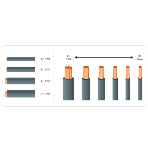
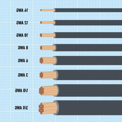
The American Wire Gauge (AWG) system provides Wire sizes through its standard wire size classification system. The rating system establishes an inverse relationship between wire thickness and gauge number because lower gauge numbers (for example 6 AWG) represent thicker wires that deliver higher current capacity while higher gauge numbers (for example 14 AWG) represent thinner wires that deliver lower current capacity. The following table provides common wire sizes together with their respective ampacity values as a reference guide.
⭐ Recommended sizes for 40 Amp circuits
Factors That Influence Wire Size Selection
- ⚡The wire requires selection based on its ability to conduct electrical current through its designated current carrying capacity. The wire will overheat when its ampacity limit gets exceeded which creates fire danger because the wire becomes too hot to handle.
- 📏The resistance created by extended wire runs results in substantial voltage loss. Electrical conductors need to use thicker wires for longer distances because they require lower AWG wire sizes to handle electrical current.
- 🔧The industry primarily uses copper and aluminum as their main conductor materials. Copper surpasses aluminum in electrical conductivity and ampacity but its higher price makes it less affordable.
- 🌡The insulation used on wires determines their capability to withstand different environmental conditions and temperature extremes. Wire insulation must always be chosen according to local codes and standards requirements.
- 📜The National Electrical Code (NEC) provides detailed guidelines and tables for determining wire size based on different circuit types, conductor counts, and conditions. The standards establish the legal requirements which must be fulfilled to operate the system safely at all times.
Applications of Common Wire Sizes
- 14 AWGThe wire size functions properly for both lighting circuits and residential systems that require low power.
- 12 AWGThe wire size functions properly for kitchen appliances and small heaters and all general household outlets.
- 10 AWGThe wire size serves as the standard for connecting air conditioning units and water heating systems and electric clothes drying machines.
- 6 AWGThe wire size connects industrial strength electrical equipment which includes stoves and sub-panel systems.
- 2 AWG+The wire sizes serve as the standard for main service entrance cables and feeder line systems.
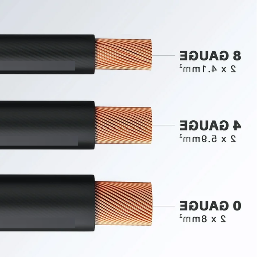
Comparison of 8 AWG vs. 6 AWG
The comparison between 8 AWG wires and 6 AWG wires requires an assessment of their unique attributes and their intended uses. Here is a thorough explanation of essential elements which need examination:
Copper vs. Aluminum Conductors
The process of choosing electrical conductors needs a comparison between copper and aluminum which requires an assessment of their unique properties and advantages along with their respective shortcomings.
Copper Conductors
Copper serves as the primary material for electrical wiring because it delivers both excellent electrical conductivity and strong physical attributes. The three main advantages of copper conductors include the following:
- High Conductivity: Copper offers a conductivity of approximately 97% of the International Annealed Copper Standard (IACS), making it highly efficient for electrical energy transfer.
- Strength & Durability: Copper maintains its strength together with its durability because it can withstand both mechanical stress and high-temperature conditions.
- Corrosion Resistance: Copper exhibits strong resistance to oxidation and corrosion which makes it more durable than aluminum although it does not provide complete protection against these issues.
The industry uses copper for residential wiring and industrial power distribution and all situations where dependable operation needs to be maintained throughout the system.
Aluminum Conductors
Aluminum remains a popular choice because it delivers two benefits through its lightweight properties and lower costs while engineers view its electrical performance as inferior to copper. The material exhibits these essential properties:
- Weight and Cost Efficiency: Aluminum is significantly lighter and less expensive than copper which leads to material cost reductions that reach 40% in many cases.
- Lower Conductivity: Electricians need to use larger wire sizes because aluminum maintains 61% of copper’s conductivity for equal current transmission.
- Expansion and Oxidation: Aluminum exhibits greater thermal expansion and contraction than copper which creates potential connection problems that need correct installation methods to solve. The material oxidizes more quickly which necessitates the use of suitable anti-oxidant protective coatings.
- Applications: Aluminum conductors find their main usage in power transmission lines that operate at utility scale and in major projects which require budget reductions to achieve success.
Performance Comparison
💡 Key Considerations
The Copper material shows suitability for installation in small areas which experience constant temperature changes because of its structural strength and ability to withstand thermal expansion. The proper installation and maintenance of aluminum systems are essential to prevent connection problems from arising.
The project will benefit from aluminum as the main construction material because its lower costs match requirements for large utility projects. The selection process between copper and aluminum conductors requires assessment of project requirements which include financial constraints and performance needs and environmental factors. The selected conductor material requires installation and maintenance procedures to establish safety and operational efficiency.
Wire Gauge Chart for 40A Current
The task of choosing an appropriate wire gauge to handle 40 amps requires both safety measures and efficiency standards. The American Wire Gauge (AWG) system provides a standardized measurement to determine the conductor size suitable for various current loads.
Copper Wire
8 AWG
Minimum recommended for 40 amp copper circuits. Provides superior conductivity and durability for dependable performance.
Aluminum Wire
6 AWG
Minimum required for 40 amp aluminum circuits. Thicker gauge compensates for lower conductivity while remaining cost-effective.
Long Distance Runs (50+ ft)
Upsize
Use 6 AWG copper or 4 AWG aluminum for long runs to control voltage drop and maintain operational efficiency.
Key Considerations for 40 Amp Circuits
The 40 amp circuit installation process requires several safety requirements which must be followed to achieve operational efficiency and to meet safety regulations. The following sections describe five essential elements which require implementation.
Proper Wire Size
The correct wire gauge should be used to establish a 40 amp circuit. The circuit requires 8 AWG copper wire or 6 AWG aluminum wire to safely carry the current without overheating.
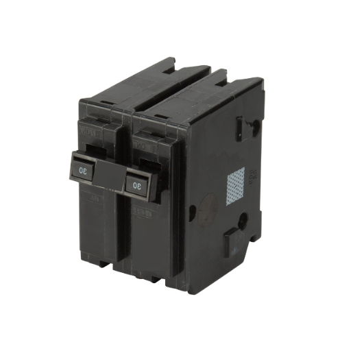
Circuit Breaker Rating
The circuit breaker needs a 40 amp rating because it protects the 40 amp circuit from hazardous electrical overloads which can cause fires.
Appliance Compatibility
The circuit needs verification that its connected appliances and devices can handle a 40 amp power supply. The circuit will experience overloading when devices which do not match its specifications are used with it, resulting in equipment failures and dangerous situations.
Voltage Requirements
You must match circuit voltage to your application needs which require both 120V and 240V and other standard voltages because voltage determines circuit functionality and security.
Environmental Factors
Environmental factors, which include ambient temperature and moisture exposure, must be assessed because they impact both wire insulation and the performance of entire electrical circuits. The organizations need to use temperature-rated wires together with appropriate protective conduits to handle these environmental conditions.
The 80% Rule for Continuous Loads
The 80% rule functions as a fundamental guideline which professionals use to design electrical circuits and establish safety standards. The rule establishes that a circuit should handle no more than 80% of its maximum load capacity during continuous operation. The rule becomes essential for circuits which need to run without interruption for three hours or longer because extended operation creates heat which affects the wires and insulating materials. The system operates at an increased danger of equipment overheating which results in both equipment destruction and fire risks when users exceed established operational limits.
A standard 20-amp circuit should restrict its maximum continuous load to 16 amps which equals 20 amps multiplied by 0.8 limit. A 15-amp circuit should not carry a continuous load of more than 12 amps. The National Electrical Code (NEC) requirements together with safety needs get satisfied through this approach.
The 80% Rule Formula
Maximum Continuous Load = Circuit Amperage × 0.80
Example: 40A × 0.80 = 32 Amps maximum continuous load
Why the 80% Rule Matters
Overheating Protection
Electrical components which include wires and circuit breakers and outlets need to handle their maximum current limits according to their design specifications. Equipment which operates at its maximum capacity during continuous use will experience two results which include performance deterioration and equipment breakdown. Heat control becomes efficient when load requirements stay below 80% because this level allows effective system operation.
Equipment Lifespan Preservation
The lifespan of electrical devices gets shortened when circuits reach their maximum capacity. The 80% load limit enables components to operate with reduced stress which results in fewer early breakdowns.
Code Compliance
The NEC Article 210.19 A 1 branch circuit system utilizes the 80% rule as its standard. Inspections trigger when organizations fail to comply with regulations which either result in inspection failure or mandate costly system modifications for lawful operation.
The 80 percent rule protects your electrical system by increasing safety and extending operational life while reducing all potential hazards. The design process requires you to work with a licensed electrician who will verify your project complies with all regulations and design requirements.
Impact of Voltage Drop and Wire Length
Electrical systems need to consider voltage drop and wire length because both elements impact system performance and safety measures. Wires experience voltage decline because electrical current encounters resistance from the conducting material. The voltage drop problem becomes worse when wires extend over greater distances and the conductor material fails to meet required dimensions. The following section presents five essential facts and measurements that demonstrate how voltage drop and wire length affect electrical systems.
Voltage Drop Formula
Voltage Drop (V) = (2 × L × I × R) / 1000
- L = Wire length in feet
- I = Current in amperes
- R = Resistance value of conductor per 1000 feet
- 1
Standard Voltage Drop Recommendation: Most codes require that branch circuits should maintain a maximum voltage drop of 3 percent while combined branch and feeder circuits must limit their voltage drop to 5 percent.
- 2
Impact on Equipment Performance: Excessive voltage drop causes equipment to operate at a voltage lower than it was designed for which leads to efficiency loss and equipment overheating and electrical devices experiencing shortened lifespans.
- 3
Wire Size and Material: Electrical resistance decreases through the use of larger wire sizes and copper high-conductivity materials which results in voltage drop reduction. A 4 AWG copper wire exhibits significantly lower resistance per foot than a 10 AWG wire made from the same material.
- 4
Voltage Drop vs. Distance: Long wire runs lead to increased voltage drop. A 120V circuit carrying 10 amps over 100-foot copper wire will experience a 3.8V drop through a 12 AWG conductor while a similar 10 AWG conductor will drop only 2.4V under identical conditions.
The selection of proper wire size and material together with application-specific planning enables organizations to handle voltage drop problems while maintaining stable network performance throughout their electrical systems.
Common Applications for a 40 Amp Circuit
Electrical systems which require increased power capacity use 40 amp circuits in residential areas and commercial buildings and industrial production facilities. The 40 amp circuit shows five standard uses which contain both operational details and essential technical information.
Technical Specifications for Wiring
Electric wiring systems need to follow established technical standards because this approach protects safety and system performance while complying with regional legal standards. The following specifications and requirements form the basis of the project implementation process.
1. Wire Size and Ampacity
The wire gauge needs to match the current carrying capacity of ampacity to stop wires from overheating which creates fire hazards. The following common examples demonstrate this point:
- 12 AWG: This wire gauge can handle 20 amps which works in general lighting and receptacle circuits.
- 10 AWG: This wire gauge can handle 30 amps which people use to power electric water heaters and air conditioners.
- 8 AWG: This wire gauge can handle 40 amps which people use to power large appliances and electric vehicle charging stations.
- 6 AWG: This wire gauge can handle 55 amps which people use to power devices such as subpanels and welders.
2. Voltage Ratings
Wires need insulation which matches the operating voltage requirements of their circuits.
- 600V Insulated Cables: Standard for residential and commercial applications.
- 1,000V or Higher Insulation: Used in industrial settings and solar panel installations.
3. Temperature Ratings
Wire insulation materials must handle the maximum operating temperature in the environment. The following common ratings include:
- 60°C (140°F): Found in older installations.
- 75°C (167°F): Modern residential systems use this standard which requires thermoplastic PVC insulation materials such as THW or THWN.
- 90°C (194°F): This temperature rating applies to applications that require high thermal performance which includes LED lighting deployments and industrial equipment.
4. Conduit and Cable Installation
Proper conduit sizing requires accurate measurements because it determines airflow rates which protect equipment from overheating. The NEC code allows maximum conduit fill to reach 40 percent of total cross-sectional space according to their regulations.
- Rigid Metal Conduit (RMC) provides better protection for outdoor electrical wiring systems.
- PVC Conduit delivers affordable and lightweight protection which requires proper sealing to function in indoor and outdoor spaces.
5. Grounding Requirements
The system needs a reliable grounding system which provides protection by channeling fault currents away from working equipment.
- Copper Grounding Wire operates as the most common selection because it delivers better electrical conductivity than other materials.
- The minimum size requirements include fourteen AWG for fifteen amp circuits and eight AWG for all other equipment.
6. Special Considerations for EV Chargers
Level 2 EV chargers typically require:
- 240V Circuit: This connection enables high-powered charger devices to work effectively.
- Dedicated Circuit Breaker: Most home chargers need a 40-amp circuit breaker which suits devices like Tesla Wall Connector and ChargePoint Home Flex.
7. Smart Wiring Systems
Homeowners today choose smart wiring systems which use structured cabling to create smart home networks that operate their IoT devices and security systems and home automation control systems.
- Category 6 Cables: Recommended for high-speed internet and smart devices.
- Fiber Optic Options: Provide future-proof wiring for high-bandwidth needs.
The combination of these specifications with contemporary practices, including advanced fireproof conduits and intelligent monitoring systems, will improve the efficiency of wiring systems because they will meet the demands of contemporary life. The installation process requires you to follow current standards which include NEC 2023 for any new work or system upgrades.
Insulation Types: THHN, NM-B, and More
The selection of wiring for a project requires knowledge about existing insulation types because those types determine the system’s safety characteristics and operational efficiency and its lifespan. The following list presents common insulation types together with their specifications and current information.
Thermoplastic High Heat-Resistant Nylon-Coated
THHN wires show their adaptability through widespread application in both building projects and operational control systems. The wires can withstand heat up to 90°C when used in dry spaces and they permit installation through conduit systems. The nylon coating protects THHN wires from industrial use because it defends against abrasion and chemical exposure and water damage. The recent specifications show that they fulfill UL 83 standards which indicate their compliance with safety regulations.
Non-Metallic Sheathed Cable, Type B
NM-B cables serve indoor residential wiring purposes through their design which includes two or more conductors that are protected by a thermoplastic sheath. The materials of the product can withstand dry conditions while maintaining operational capacity at temperatures that reach 90°C. The NM-B cables enable users to create indoor lighting systems and power circuits which run through walls and ceilings. The products offer users affordable pricing and simple installation procedures but users should avoid using them in wet conditions or outdoor spaces.
Underground Feeder, Type B
The design of UF-B cables enables their installation in outdoor and underground environments because their construction allows for direct burial which differs from NM-B cable design. The cables maintain their functionality because they can withstand both moisture and ultraviolet radiation, which makes them appropriate for operating outdoor lights and supplying power to underground connections that lead to separate buildings.
Cross-Linked Polyethylene High Heat-Resistant Water-Resistant
The wire insulation type shows its optimal performance under conditions of wetness and when exposed to materials that cause corrosion. XHHW wires can handle higher temperature ranges (up to 90°C in wet conditions and 105°C in dry situations). The materials serve industrial applications because they need to maintain strength and reliability.
Thermoplastic Flexible Fixture Nylon
The lightweight and flexible design of TFFN wires makes them appropriate for use in light fixtures and small appliances. The materials provide heat resistance up to 90°C, which makes them ideal for use in environments with limited spatial availability.
Your selection of insulation type will protect your wiring systems through safe operation and extended system durability. You must use the most recent information from NEC 2023 and manufacturer data sheets to determine which components will operate correctly with your specific needs.
Temperature Ratings and Their Importance
Engineers use temperature ratings as essential factors to select electrical wiring materials and insulation products. The ratings show the highest temperature which a material can function without its properties being damaged and its performance being compromised. Electrical systems require correct temperature rating understanding because it determines their capacity to operate and their ability to maintain structural integrity and their safety during operation. The following list presents five essential temperature ratings which determine their importance for electrical insulation materials.
60°C / 140°F
This rating exists in current usage but only applies to older wiring systems which were designed for low-energy residential needs.
75°C / 167°F
This rating exists as the standard for residential and commercial wiring applications which handle general circuits together with medium electrical loads.
90°C / 194°F
This rating serves as the standard for contemporary wiring systems which operate in areas with elevated temperatures and power circuits that carry heavy electrical loads. The material provides two benefits through its superior heat protection and flexible design.
105°C / 221°F
The material exists as a solution for specialized industrial needs which appear in lighting systems and electrical devices and manufacturing facilities that face extreme temperature conditions.
125–150°C
These temperature ranges find application in industrial systems and automotive systems and aerospace systems which need high-performance materials. The materials withstand extreme temperature conditions which industrial environments and automotive systems and aerospace systems experience.
The process of selecting and applying the correct temperature rating requires proper temperature rating selection which guarantees electrical systems will function correctly throughout their operational lifespan. All material selections must consider both environmental temperature conditions and required safety margin protection.