The correct wire size selection for a 50 amp circuit construction work requires proper execution because it directly impacts both safety measures and operational efficiency of electrical work. The performance of your new appliance installation and your electrical system upgrade and your DIY project will suffer because you used the wrong wire size. This guide provides you with complete information about choosing the correct wire size for a 50 amp circuit which will help you understand the process which seems difficult at first. The project will give you knowledge to choose appropriate wiring which meets safety standards and follows electrical code requirements.
Introduction to 50 Amp Circuits
A 50 amp circuit is commonly used in residential and commercial settings to power high-demand appliances, such as electric ranges, large air conditioners, or RVs. For equipment that requires more energy than standard circuits provide the system supplies power through its 240 volt operation. The correct wire size selection keeps the system safe while providing optimal performance because 6-gauge copper wire becomes the standard recommendation for 50 amp circuits. The electrical installation process requires strict adherence to local electrical codes and standards to protect against risks and ensure operational efficiency.
The Importance of Electrical Safety
Electrical safety exists as a mandatory requirement which all residential spaces and professional work environments and industrial facilities must follow. The implementation of appropriate safety measures requires organizations to comprehend their functions because these measures protect people from accidents and injuries and deaths. The Electrical Safety Foundation International reports that there are about 30,000 electrical shock incidents which happen in the United States every year so they need to develop better safety awareness programs. The following five factors represent essential elements which people need to consider for their electrical safety maintenance procedures.
1. Use the Proper Equipment
All electrical devices should match their intended functions while meeting established safety requirements. For example, vulnerable areas such as kitchens and bathrooms require the installation of surge protectors and ground-fault circuit interrupters (GFCIs).
2. Inspect Wiring Regularly
The presence of damaged or frayed wires creates a major safety risk. The inspection schedule must be established to assess the operational status of all building wiring systems particularly in older structures.
3. Avoid Overloading Circuits
Excessive device connection to one electrical outlet or power strip results in overheating which can cause electrical fires. To prevent equipment damage, distribute electrical usage across multiple circuits.
4. Follow Electrical Codes
The compliance with both local and national electrical standards guarantees that all electrical work fulfills required safety standards. This procedure helps to maintain safe operational conditions by decreasing the possibility of short circuits and other electrical system dangers.
5. Educate and Train Individuals
All employees operating electrical equipment in workplace environments need to receive safety training. People save lives during emergencies when they know about potential dangers and correct emergency response procedures.
The implementation of these guidelines enables both individuals and organizations to create safer work environments which minimize electrical system dangers.
Understanding Wire Size and Ampacity
The correct determination of wire size together with its associated ampacity values establishes essential requirements which electrical systems must meet for safe operation and efficient performance. The term ampacity describes the highest electrical current level which a wire can conduct without experiencing thermal damage that needs to be measured in amperes. The selection of appropriate wire dimensions for specific use cases acts as a safeguard against overheating conditions while decreasing energy consumption and minimizing fire hazards.
Wire Gauge and Ampacity Ratings
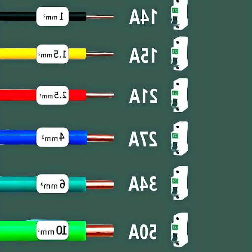
The American Wire Gauge (AWG) system serves as the standard measurement system for wire size because it uses smaller wire diameter numbers to indicate bigger wire sizes. For instance:
- The 14 AWG wire can carry 15 amps which makes it suitable for use in lighting circuits.
- The 12 AWG wire supports an ampacity of 20 amps which makes it perfect for use in standard electrical outlets.
- 10 AWG wire with an ampacity of 30 amps is often used for larger appliances like air conditioners.
- 8 AWG wire has an ampacity of 40 amps which makes it suitable for use with electric ovens and other devices that require high current.
The wire ratings require the wires to function under both standard ambient temperature conditions and proper insulation protection. The actual temperature conditions together with the insulation material used and the specific installation factors that include wiring through conduits will create changes in these measurements.
Essential Elements Which Ensure Proper Installation Safety
Temperature Ratings
- Every wire insulation type has a specific maximum temperature which designers created for its protection. The maximum efficient operating temperature of THHN insulation reaches 90°C (194°F) because this temperature represents its optimal functioning conditions.
- The maximum temperature limit for NM-B (Romex) wiring which people use for residential electrical work reaches 60°C (140°F) unless the manufacturer specifies different temperature limits.
Voltage Drop
Wires produce electrical resistance which causes voltage drop through longer distances and this results in reduced operational efficiency for electrical devices. Engineers recommend larger wire sizes for circuits which extend beyond 50-foot lengths to address this problem.
Environment and Safety Codes
Electric wires that operate in outdoor or wet areas need special design methods. The direct earth burial capacity of UF-B cables allows underground installation while MC cables deliver additional mechanical protection.
National Electrical Code (NEC) Compliance
The NEC establishes mandatory wire size regulations together with required ampacity standards which depend on three factors: current capacity, environmental conditions, and application methods. The NEC ampacity charts must be used by electricians and engineers to design electrical systems and perform inspections because these charts provide necessary information for compliance.
NEC Ampacity Chart — Copper Conductors
| Wire Size (AWG) | Ampacity (60°C) | Ampacity (75°C) | Ampacity (90°C) |
|---|---|---|---|
| 14 AWG | 15 amps | 20 amps | 25 amps |
| 12 AWG | 20 amps | 25 amps | 30 amps |
| 10 AWG | 30 amps | 35 amps | 40 amps |
| 8 AWG | 40 amps | 50 amps | 55 amps |
Final Thoughts: Electric systems function properly when users understand wire size relationships with ampacity because this knowledge prevents dangerous situations that cause overheating and fire hazards. The correct wire size for your particular application should be determined through consultation with a licensed electrician or the current NEC standards. The combination of proper planning together with strict adherence to safety regulations establishes the foundation for both reliable and safe electrical installations.
Wire Gauge Requirements for 50 Amp Circuit
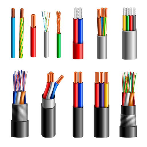
The process of selecting the correct wire gauge for a 50 amp circuit design needs to guarantee both safety standards and electric code requirements. According to the National Electrical Code (NEC) regulations 50-amp circuits must utilize at least 6 AWG (American Wire Gauge) copper wire or 4 AWG aluminum wire for their electrical connections. The wire sizes provide specific ratings which enable safe amperage handling without causing excessive voltage drop or wire overheating.
🔶 Copper Wire
The standard wire for a 50-amp circuit uses 6 AWG copper wire because it offers exceptional electrical conductivity and high-temperature resistance. Copper wires are often preferred because they maintain their strength and efficiency even when used in demanding situations which include operating electric ranges and heavy power tools and charging electric vehicles.
🔷 Aluminum Wire
For a 50-amp circuit the required aluminum wire size is 4 AWG. Aluminum wire costs less and weighs less than copper wire but its lower conductivity requires users to install thicker wires for identical current transmission needs.
Voltage Drop Considerations
Voltage drop becomes an essential consideration for circuits that extend across long distances. The total run needs to exceed 100 feet because smaller wires will result in energy waste. The system will achieve better performance and safety outcomes when it upgrades to 4 AWG copper or 2 AWG aluminum under these specific conditions.
Common Applications
The 50-amp circuit provides electrical power to multiple high-demand devices which include:
- Electric water heaters
- Subpanels
- Large RVs or recreational vehicle hookups
- EV charging systems
- Welders and workshop equipment
Safety Precautions
The insulation of the wire must match the installation environment which includes outdoor conditions, underground sites, and high-temperature areas. The safest results require the use of UL-listed wires together with the complete following of local code requirements.
Key Takeaway: Proper wire sizing is necessary to achieve both efficient electrical installations and safe operation of those systems. Electricians who hold licenses should be consulted when you need to assess which wire gauge should be used with your 50-amp circuit because environmental factors and distance requirements need to be considered.
Comparing 6 AWG vs 8 AWG Wire Size
Your project requires you to select the better wire size between 6 AWG and 8 AWG after you investigate the strengths and weaknesses of both wire sizes. The two wire sizes serve as standard wiring solutions for both residential buildings and commercial locations, yet their specifications show distinct differences in amperage handling capabilities and physical characteristics and pricing structure.
Key Differences Between 6 AWG and 8 AWG Wires
| Specification | 6 AWG Wire | 8 AWG Wire |
|---|---|---|
| Amperage Rating | Up to 55 amps | Up to 40 amps |
| Diameter | 0.162 inches (4.11 mm) | 0.1285 inches (3.26 mm) |
| Voltage Drop | Lower over long distances | Higher over long distances |
| Cost | More expensive | More affordable |
| Applications | High-demand appliances, long runs | Smaller appliances, short runs |
Summary: The 6 AWG wire serves as the better option for 50-amp circuits because its higher amperage capacity and lower voltage drop performance make it superior to 8 AWG wire. The 8 AWG wire becomes a budget-friendly option when the circuit requires less power and needs to operate within shorter distances. The installation needs both a licensed electrician and local code requirements to ensure safety and compliance.
Copper vs Aluminum Wire for 50 Amp Circuits
The decision between using copper or aluminum wire for a 50-amp circuit requires evaluating both materials through their electrical performance and their financial and operational factors. The selection process between two materials requires attention to these five essential elements.
Electrical Conductivity
Copper has higher electrical conductivity compared to aluminum which enables it to transmit identical electrical currents using smaller wire dimensions. The energy waste of electric power distribution systems decreases with this characteristic which makes copper the most effective material for distribution systems.
Durability
Copper exhibits exceptional strength which enables it to withstand damage while its resistance to corrosion exceeds that of aluminum. The material is used in circuits which need to last for extended periods or in places where the wiring faces direct water exposure.
Cost
Aluminum prices are much lower than copper prices making it the most cost-effective option for large-scale electrical installations. The cost benefits of aluminum wiring may disappear because of the additional safety equipment needed to handle this type of electrical installation.
Weight
Aluminum has a weight that is much lighter than the weight of copper. Aluminum wire becomes easier to handle and install because its weight is lower which creates essential benefits during lengthy industrial installations and work with thick wires.
Thermal Expansion
Aluminum undergoes greater temperature-induced expansion and contraction compared to copper. The specific installation method and scheduled maintenance activities are necessary to guarantee connection stability which protects against potential safety hazards.
Factors Influencing Wire Size Selection
The process of selecting suitable wire dimensions for a particular application needs testing of multiple factors which establish operational safety requirements and performance standards and compliance with regulations. The following five elements direct the process of choosing wire dimensions for various applications:
Current Carrying Capacity (Ampacity)
The ampacity of a wire defines its maximum electrical current capacity which it can transmit without experiencing overheating. The ampacity of a wire depends on four factors which include its material composition and gauge specifications and insulation type and the surrounding temperature. A 14-gauge copper wire has an ampacity of 15 amps which allows it to carry 15 amps, but the same gauge of aluminum wire might carry a slightly lower current.
Voltage Drop
The voltage drop of an electrical circuit occurs when its final voltage reading at the circuit end point drops below the initial voltage level, which exists at the power source because of wire resistance. The use of longer wire runs together with smaller conductors results in voltage drops which create operational problems and lead to equipment breakdowns. To reduce voltage drop problems operators need to use larger wire sizes during their operations which apply to long-distance wire installations.
Environmental Conditions
The installation environment plays a critical role in wire size selection. The wire insulation and operational capabilities of a wire system will experience alteration from factors which include temperature and humidity and chemical contact. The industrial applications and outdoor operations require conductors to have larger dimensions together with strong insulation materials which protect against extreme environmental conditions.
Load Type and Duration
The selection of wire size requires evaluation of electrical load types which include both continuous loads and intermittent loads together with their specific time requirements. Continuous loads that operate beyond three hours require electrical systems to use larger wire gauges for safe operation and continuous performance.
Code and Regulatory Compliance
The National Electrical Code (NEC) together with other electrical regulations in the United States establishes rules which electrical professionals must follow to determine wire sizes based on different application needs and safety standards. Organizations that follow these standards will fulfill their legal requirements while they reduce the chances of dangerous situations that could result in electrical fires or equipment destruction.
The 80% Rule and Continuous Loads
80% Rule
Circuit breakers should operate at no more than 80% of their maximum rated capacity
The 80% rule establishes a core guideline which electrical engineers use to design systems that protect against risks while maintaining operational effectiveness for ongoing power consumption. The National Electrical Code (NEC) defines continuous load as any electrical load which runs at its highest current level for three or more hours. The definition includes continuous-running lighting systems and HVAC systems and industrial machines which operate without interruption.
The NEC establishes a 80% circuit capacity limit because it wants to protect against overheating risks and circuit overload dangers which occur in circuits that transmit continuous power. A 20-amp circuit has a continuous load limit of 16 amps which the system allows (20 × 0.8 = 16). The electrical system uses this free capacity to manage small power surges and voltage changes which would otherwise cause breakers to trip or wires to overheat.
The sizing of wires and breakers requires assessment of how this rule will impact operations. The 80% rule requires residential and commercial lighting systems to select circuit breakers and cables which can support their current power needs and any future system expansions.
Calculating Continuous Load
Continuous Load = Total Wattage ÷ Voltage
A commonly referenced equation is:
A 120V system with 1,200 watts of lighting fixtures draws: 1,200 ÷ 120 = 10 amps
The circuit should have a rating of at least: 10 ÷ 0.8 = 12.5 amps
The minimum breaker size which this case requires ranges from 15 amps to higher sizes.
Calculations require additional code compliance requirements and environmental temperature conditions which determine necessary wire sizes and equipment strength.
The 80% rule enables circuit designs to create more durable systems which improve operational reliability for both residential and commercial applications.
Calculating Ampacity for Continuous Loads
The 80% rule must be applied when you calculate ampacity because this rule ensures your circuit will work safely during permanent operation. According to the National Electrical Code (NEC) definition a continuous load constitutes a load which will draw its maximum current during a three-hour period or longer. The 80% rule requires a conductor or circuit breaker to have an ampacity which exceeds the continuous load current by 125%.
The Formula for Calculating Ampacity:
Ampacity = Continuous Load Current × 1.25
Example: 16 amps × 1.25 = 20 amps minimum required
Data Application Examples
| Continuous Load | Calculation | Required Breaker |
|---|---|---|
| 12 amps | 12 × 1.25 | 15 amps or higher |
| 24 amps | 24 × 1.25 | 30 amps or higher |
| 40 amps | 40 × 1.25 | 50 amps or higher |
Additional Considerations
Temperature Rating
The conductor insulation must match the requirements of the operating environment. The ampacity of conductors in environments which exceed their temperature rating must be reduced through derating.
Voltage Drop
Long wire runs create voltage drop problems because they cause significant electrical resistance. The system requires larger wire sizes because voltage drop issues need resolution despite the calculated ampacity appearing sufficient.
Matching Load Equipment
All equipment that connects to circuits must match the calculated ampacity value which prevents equipment failures. The designers and electricians can achieve NEC compliance through their environmental factor assessments and calculation procedures which create safer and more efficient electrical systems.
Common Applications for 50 Amp Circuits
The additional power requirements of the spaces which include residential, commercial and recreational areas can be fulfilled through 50 amp circuits which provide their needed electrical capacity. The circuits enable electrical loads to reach their maximum capacity of 50 amps which allows them to deliver electricity for high-demand equipment and industrial machinery.
The implementation of 50 amp circuits in these systems enables users to achieve efficient and safe operation of their devices. The widespread use of 50 amp circuits across various applications became evident in 2022 when 1 million U.S. households reported using these circuits for their RVs according to industry data.
EV Chargers and Electric Vehicles
The worldwide shift toward sustainable practices which aim to reduce carbon emissions has led to an accelerated rise in both EV charger installation and electric vehicle adoption during the past few years. Electric vehicle (EV) chargers function as essential components to facilitate this transition because they deliver the necessary infrastructure which enables efficient vehicle operation. The latest market research shows that the global EV charger market reached a valuation of approximately $24 billion in 2022 and will expand to more than $150 billion by 2030 with a compound annual growth rate (CAGR) exceeding 25%.
EV Charging Levels
Level 1
Standard 120-volt outlets, suited for overnight home charging.
Level 2
Operates at 240 volts for much higher recharging speeds.
Level 3 (DC Fast)
Achieves 80% battery power in 20–30 minutes at commercial/public stations.
Governments worldwide are investing significant amounts of money into electric vehicle charging infrastructure projects which help them achieve their goal of making electric vehicles more widely accepted. The U.S. government Bipartisan Infrastructure Law has designated $7.5 billion to establish a nationwide electric vehicle charging system which will install 500,000 charging stations throughout the country by 2030. The European Union plans to operate 1 million public charging stations by 2025 which will meet the growing demand of electric vehicle drivers in Europe.
The rise in EV use is reflected in the growing sales of electric vehicles, which reached an estimated 10 million units globally in 2022, marking a 55% increase from the previous year. The increase in electric vehicle sales results from the improvements in battery technology which enable electric vehicles to drive longer distances while using less energy. The worldwide transition to electric vehicles depends on two major factors which drive forward development and installation of electric vehicle charging networks.
RV Hookups and Recreational Use
RV hookups serve as essential facilities which allow RV users to travel with their vehicles because they establish vital connections to water and electricity and sewage systems which permit users to operate their vehicles. The three main types of RV hookups found at campsites or RV parks include:
- Full Hookups — These include connections for water, sewer, and electricity. The electricity service provides 30- and 50-amp connections which meet the needs of different RV models. Full hookups attract both permanent residents and travelers who want the easiest access to their destinations.
- Partial Hookups — The systems provide visitors with access to water and electricity but they do not provide a means to dispose of sewage. The site provides on-site dump stations which travelers can use for wastewater management purposes.
- Dry Camping (Boondocking) — The practice involves camping at sites which do not provide any utility connections. RV users who want to camp without electricity must depend on their built-in battery and their onboard water supply and on their wastewater storage tanks.
The RV industry currently experiences rapid growth because 11.2 million American households owned an RV in the United States as of 2023. The number of RVers who choose to camp at sites with modern hookups continues to grow because they find these facilities advantageous. Research shows that more than 57% of RV drivers choose full hookup campsites because they want to have a simple experience using the facilities. Campgrounds now install solar-powered hookups and advanced water-saving systems because they want to attract environmentally minded travelers who follow sustainability trends in the industry.
The growing popularity of outdoor activities in the United States is driven by RV hookups which enable national parks and state parks and private campgrounds to attract more visitors who come to see RVs.
Electric Ranges and Kitchen Appliances
The process of creating electric ranges and kitchen appliances demands cutting-edge technological innovations which produce better operational performance through easier product usage and sustainable environmental solutions. The latest Google Search data shows that the worldwide electric kitchen appliance market will experience substantial growth with a projected compound annual growth rate (CAGR) of more than 8% from 2023 until 2030. The growing demand for modern appliances which combine advanced technology with energy efficiency and contemporary design elements drives this market expansion.
⚡ Induction Cooking Efficiency
Reports indicate that induction cooking achieves an energy efficiency rate of 84%, while gas stoves reach only 40% energy efficiency.
The installation of induction cooking systems together with touch control systems and precision temperature control systems has transformed electric ranges into modern cooking appliances. Induction cooktops have gained popularity because they enable faster cooking while providing superior temperature control and lower energy consumption. Smart connectivity has become a vital requirement for customers because they want to control their cooking operations through Wi-Fi-enabled devices which support app functions and special cooking options.
The development of AI-enabled refrigerators and dishwashers and microwaves has led to the creation of advanced kitchen appliances which operate through voice commands and environmentally friendly modes. The purpose of these innovations is to create user-friendly systems which handle practical tasks while minimizing energy usage to fulfill worldwide sustainability objectives. The energy-efficient dishwashers in the industry market offer consumers water savings of up to 20% which exceeds the performance capabilities of standard dishwashing machines.
The increasing adoption of electric ranges and modern kitchen appliances proves that households throughout the world are using sophisticated kitchen technology which develops sustainable cooking environments and delivers simpler cooking methods.
Voltage Drop Considerations
The electrical system needs voltage drop measurements because they provide essential data which determines both system performance and safety. The resistance of a material causes voltage loss in a conductor when electricity travels through it. The following section identifies five essential factors which need to be studied in order to decrease voltage drop:
Conductor Length
Longer conductors create increased voltage drop. The total circuit length needs to be calculated because it includes both the forward path and the return path for current.
Conductor Material
Different materials show varying electrical resistivity. Copper is the preferred conductor material because it has lower resistance.
Conductor Size
Higher wire gauge sizes produce decreased circuit resistance which results in lower voltage drop. Engineers use wire size selection to match current needs.
Operating Current
The voltage drop increases when the circuit carries higher current. Proper conductor sizing is required while using shorter paths to reduce electrical losses.
Connection Quality
The circuit faces increased resistance from poorly made connections which include terminals that are loose or have corrosion damage.
Precise methods need to control the factors because their direct relationship with voltage drop affects both system reliability and operational efficiency across various electrical system applications.
Understanding Voltage Drop in Long Runs
The electricity distribution system suffers from voltage drop problems because electric circuits require long-distance operation. The phenomenon occurs when electrical current travels through a conductor and encounters resistance which results in voltage loss between the source and the load.
Three Main Factors Determining Voltage Drop
- Different wire materials exhibit different resistivity properties which results in different conductor resistivity values. Copper serves as a better electrical conductor than aluminum which makes it more effective at minimizing voltage drop.
- The electrical resistance of longer cable runs will create more voltage drop because longer distances require more electrical resistance. The voltage drop in a 200-foot circuit exceeds the voltage drop in a 50-foot circuit.
- The voltage drop in the circuit depends on the current load which determines how much current the circuit carries. The system experiences more resistance and energy losses when higher current levels occur.
The cable cross-sectional area appears as the most crucial factor in determining wire size. Thicker cables (lower gauge numbers) reduce resistance which results in decreased voltage drop.
📊 Practical Example
The 12-gauge copper wire which carries a 20 ampere current across 100 feet of distance produces a 3.2 volt voltage drop for a 120 volt system which results in a 2.67 percent voltage loss.
The National Electrical Code (NEC) recommends branch circuits should maintain voltage drop below 3 percent because this level ensures efficient operation of electrical systems.
Mitigation Strategies
- Upgrade Conductor Size: For longer runs, choosing a larger gauge wire is the simplest solution. The resistance of a circuit reduces when a 12-gauge wire system gets upgraded to a 10-gauge wire system.
- Optimize Circuit Design: The reduction of extra circuit length together with direct routing methods helps to decrease voltage drops.
- Voltage Drop Calculators: The use of online voltage drop calculators enables electricians and engineers to create optimized systems through their ability to provide detailed equipment setup estimates.
The study of these factors enables engineers to decrease voltage drop across extended distances which permits safe and efficient operation of electrical systems in industrial, commercial and residential environments. The proper implementation of electrical systems requires engineers to follow voltage drop charts together with local electrical codes.
Calculating Acceptable Voltage Drop
Engineers must use established guidelines and industry standards to ensure electrical systems function safely while maintaining operational efficiency during their voltage drop calculations. The National Electrical Code (NEC) establishes 3% as the highest allowable voltage drop for branch circuits and feeder circuits which needs to be maintained during their regular operational period. The maximum voltage drop from feeders and branch circuits should remain under 5% because this limit is necessary for system performance and system efficiency maintenance.
Voltage Drop Formula:
Voltage Drop (V) = (2 × Length × Current × Resistance) / 1,000
- Length — one-way distance of conductor material from power source to load (in feet). For round-trip, this is multiplied by 2.
- Current — the load current which exists in amperes (A) during operation.
- Resistance — the conductor material’s resistance in ohms per kft, depending on material type and wire gauge.
Example Calculation
Imagine a scenario where a copper conductor runs 150 feet from a panel to a load carrying a current of 20 amps and the chosen wire size is 10 AWG with a resistance of 1.24 ohms/kft:
- Length = 150 feet (one-way) × 2 = 300 feet
- Current = 20 amps
- Resistance = 1.24 ohms/kft
- Voltage Drop (V) = (2 × 150 × 20 × 1.24) / 1,000 = 7.44V
If the system voltage supply reaches 120V then the percentage voltage drop will calculate as follows:
(7.44 / 120) × 100 ≈ 6.2%
⚠️ This surpasses the established limit — a larger conductor size is required.
Factors That Determine Voltage Drop
- Conductor Size and Material: The use of larger wire gauges together with copper conductors results in decreased resistance which enables better voltage drop reduction.
- Load Current: The increased voltage drop requires wiring adjustments because the higher current flow demands more wiring.
- Circuit Distance: The selection of wire for long circuit runs needs accuracy because it affects the amount of voltage loss that will take place.
- Ambient Conditions: High temperatures create elevated resistance levels in conductors which results in higher voltage drop.
Tools for Voltage Drop Calculations
Online platforms offer voltage drop calculators which provide accurate results based on user inputs of conductor material, wire gauge, current, distance and supply voltage. The Southwire tools and particular engineering applications help this process because they deliver precise forecasts. The majority of these tools provide NEC standard and local code compliance which makes them easy to use.
The process of voltage drop calculation and mitigation protects your electrical systems through enhanced durability and operational security. The most precise outcomes require you to check your calculations against local regulations and industry standards.
Frequently Asked Questions (FAQ)
References
- Cornell Law School – Legal Information Institute: 46 CFR § 183.340 – Cable and wiring requirements. This source provides detailed legal and regulatory standards for wiring requirements, including wire gauge specifications.
- University of Pittsburgh: Wire size vs breaker size. This document discusses the relationship between wire size and breaker size, including recommendations for 50-amp circuits.
- Stuyvesant High School: 50 Amp RV Breaker Box Wiring Diagram. This resource provides practical guidance on wiring for 50-amp circuits, including wire gauge recommendations.