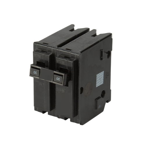
The manufacturing floor at Precision Components Ltd. experienced a complete blackout at 2:47 AM on a Tuesday. The blackout occurred because of grid failure. The blackout occurred because of an electrical system failure. The system operated as expected when the utility power supply failed because the facility backup generator started operating through its automated system. The facility maintained three essential production lines inoperable. The breaker controlling those lines displayed a green status while the operator maintained the handle in the active ON state. The breaker internal contacts had fused together during the previous months which resulted in a high-resistance circuit that failed when generator power was applied to it.
Every facility manager along with every electrical engineer needs to know this fact about circuit breakers: they can fail to operate because their internal mechanism breaks down without any evidence of malfunction. The handle stays in the ON position. The indicator shows green. The system you depend on for protection has either quietly reduced its capacity or vanished from existence.
This guide provides information about internal circuit breaker failures which lack any visible external symptoms and describes the testing methods needed to confirm breaker health before operational risks develop. Breaker failure modes are critical knowledge for personnel who control hospital life safety systems and data center essential systems and manufacturing plant production systems because these systems require continuous power supply maintenance.
Understanding Circuit Breaker Function and Failure Modes
How Thermal-Magnetic Breakers Actually Work
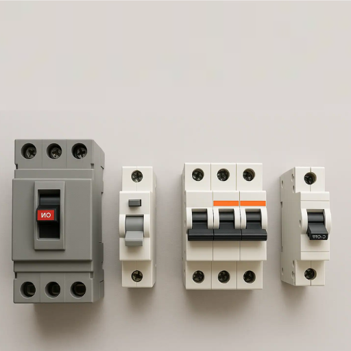
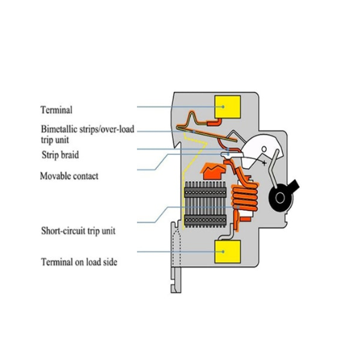
The operation of breakers that experience silent failures requires knowledge of the internal processes which occur within their plastic enclosures. A thermal-magnetic circuit breaker operates with two separate protection systems which work together to create its protective function.
The Thermal Element (Overload Protection):
A bimetallic strip heats as current passes through it. The strip bends to release a mechanical latch during sustained overloads which occur at 110-135% of rated current. This system prevents overheating which results from continuous excessive power consumption.
The Magnetic Element (Short-Circuit Protection):
The system uses a coil and armature assembly to handle high-magnitude fault currents. The system activates its short circuit protection system when the current reaches 5-10 times its rated value through the magnetic field which breaks the system within one electrical cycle.
The Critical Component Most People Ignore:
Between these protection elements and the circuit itself sits a pair of contacts. The contacts maintain full load current during ON operation of the breaker. The protection elements trip the mechanism to open the doors. The problem with this system exists because contacts can malfunction without affecting the protection system.
Why Some Failures Don’t Move the Handle
People typically visualize breaker failure as two specific problems which involve breakers that either cannot be reset or breakers that continuously trip. These issues represent two types of visible system breakdowns. Internal system breakdowns include these two hidden failure patterns. Contact welding occurs when contact points join together because of high fault currents or arcing conditions. The mechanism attempts to open when a trip command occurs but the welded contacts stay in their closed position. The handle movement depends on how severe the welding occurred because it might function or stay stationary.
- Contact erosion: Every time a breaker interrupts current, microscopic arcing erodes the contact surfaces. The contact resistance increases because erosion processes continue for multiple years of system use.
- Bimetallic strip fatigue: The thermal element can lose calibration. The device continues to trip functions although it operates at incorrect current detection thresholds. The device will reach failure when it becomes unable to create enough force to activate the tripping mechanism.
- Mechanical linkage wear: The connection between the handle and the internal mechanism can wear or break. The handle moves but the contacts remain stationary.
Yes, Circuit Breakers Can Fail Without Tripping — Here’s How
Yes, circuit breakers can go bad without tripping. The breaker becomes unable to provide overcurrent protection when internal components of the contact assembly and thermal element and mechanical linkage fail while the handle stays in the ON position. The silent failures show no obvious signs until a fault happens and the breaker fails to operate.
Internal Contact Corrosion and Welding
The electrical contacts used in circuit breakers function as silver alloy or copper components which receive protective plating. The contacts experience degradation through multiple factors which develop over time. The contact surfaces experience oxidation during humid conditions or when corrosive gases enter the area. The formation of a thin resistive layer creates a connection point which allows current to flow but produces heat. A breaker feeding a 30-amp load might develop contact resistance of 0.1 ohms. The breaker generates 90 watts of heat which continues to operate throughout its entire operational period at 30 amps.
Contact Welding Under Fault Conditions:
When breakers interrupt high fault currents, intense arcing occurs between separating contacts. If the contacts do not separate fast enough or if the fault current exceeds the breaker’s interrupting rating the contacts can weld together. The partially welded contact can still carry load current but it cannot open when a trip command occurs.
Thermal Imaging Detection:
Thermal imaging serves as a diagnostic tool which professional electrical maintenance teams use to detect electrical system problems. The temperature of a healthy breaker should rise only slightly above the surrounding temperature. Breakers with high-resistance contacts appear as hot spots in thermal images which show temperatures 20-50°C above adjacent breakers of similar loading.
Bimetallic Strip Fatigue and Calibration Drift
The thermal protection element depends on a bimetallic strip which engineers have calibrated to work with specific current-time curves. After 15-25 years of thermal cycling these strips can The metals “remember” their bent shape which reduces the force that should activate the mechanism. The mechanical connection becomes weaker The mechanical connection becomes weaker from repeated flexing. Increased resistance at connection points affects heating patterns which leads to corroding electrical joints. The thermal element which has experienced fatigue will still respond to extreme overloads but it will not activate during moderate overloads which need protection. The situation becomes dangerous because the wiring insulation overheats while the breaker remains closed.
Mechanical Handle Mechanism Failure
The external handle connects to internal contacts through multiple small plastic and metal parts. The components can fail through multiple methods which include the following:
Broken Linkage:
The handle moves freely between ON and OFF positions, but the contacts never actually open. The “phantom OFF” condition creates a situation where the circuit seems to be de-energized while it stays powered.
Partial Engagement:
The linkage connects partially, creating intermittent contact. The circuit functions properly under stable conditions, but it loses power when vibrations or thermal expansion or load changes occur. The explanation for “mystery outages” shows that power disappears because of unknown reasons.
Lubricant Hardening:
Old breakers, which operate in high-temperature environments, develop hardened lubricants throughout their internal mechanism. The thermal or magnetic trip element generates sufficient force to release the latch, but the hardened mechanism doesn’t move freely enough to open the contacts.
Common Signs of Circuit Breaker Failure (Even When Not Tripped)
Electrical Symptoms That Indicate Internal Problems
The equipment experiences random shutdowns which result in equipment either stopping function or restarting operation. The lights in the building display flickering behavior which does not match the power consumption of the building. The symptoms indicate that a combination of high-resistance contacts and loose internal connections is present which creates different thermal and vibrational effects.
Voltage Drop Under Load:
The breaker load terminal voltage must be measured using a digital multimeter. The breaker operates properly when its voltage drop measurement between line and load terminals stays below 1-2% of system voltage during full load conditions. The system requires urgent maintenance when drops reach 3-5% because this indicates the presence of high-resistance contacts and loose connections.
Flickering Lights or Equipment Malfunctions:
The voltage from the breaker contacts experiences fluctuations because of higher resistance which develops during load variations. The motors experience both power surges and speed reductions. The electronics systems experience rebooting. The LED lights experience flickering at frequencies that do not match the power system operation. The symptoms before complete breaker failure show themselves during weeks and months prior to the failure.
Unusual Breaker Temperature:
You should position your hand back to the breaker faceplate area while keeping your hand away from any conductive elements. The breaker which operates at its full rated load should produce only a mild warm sensation. Breakers which operate under identical loads to nearby breakers display extreme heat because the internal resistance system fails.
Physical Indicators of Breaker Degradation
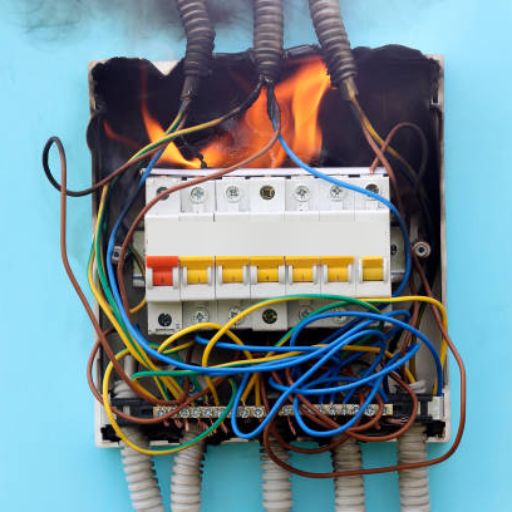
Burn Marks or Discoloration:
The breaker case needs inspection at its terminal connections. The presence of brown or black marks shows that the object has experienced excessive heat. The plastic housing shows signs of melting and deformation which require urgent breaker replacement and testing to find the actual problem.
Audible Buzzing or Humming:
Breakers which function properly produce no sound. The breaker produces a distinctive buzzing and humming sounds which show that arcing happens at the contacts because of loose internal connections. The sound produces worsens when the system handles increased weight.
Corroded or Loose Terminal Connections:
The system requires validation of the wire links which connect to the breaker terminals. Corrosion and aluminum oxide on aluminum conductors create high-resistance points which produce heat when their terminal screws become loose. The external connection problems create issues which either hide or create damage to the internal components of the breaker.
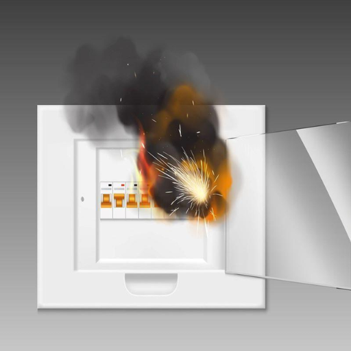
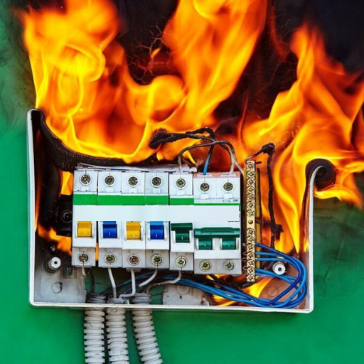
Burning Odor from the Panel:
An electrical panel produces dangerous overheating when it emits odors of burning plastic and ozone and hot metal. The situation constitutes an emergency condition. The panel needs de-energization while a qualified electrician needs to be contacted immediately.
Operational Red Flags
The handle of a breaker should move through its entire range of motion with steady resistance when you switch the breaker. Broken internal linkages cause handles to feel loose and wobble and create dead spots during their movement.
Testing Resetting Problems:
The breaker should reset to its ON position with strong spring resistance after you trip it for testing purposes or following an actual overload. Breakers with mushy operation need too much force to operate and they cannot maintain their ON position because of mechanical wear and damage problems.
Breaker Trips at Lower Than Rated Loads:
A 30-amp breaker will start tripping at 20-25 amp loads because its thermal element has lost its calibration. The breaker protection system appears too sensitive but it shows the breaker has stopped following its operational standards which requires its replacement.
Age-Related Degradation:
Commercial and industrial panels contain circuit breakers which reach their maximum operational duration. Breakers manufactured before 1990 (identified by date codes or physical appearance) should be evaluated for replacement regardless of apparent condition. Modern breakers provide 20-30 years of dependable operation under typical conditions but they age faster because of heavy cycling and high temperatures and corrosive atmospheres.
How to Test a Circuit Breaker That Isn’t Tripping
Visual Inspection Procedure
Before applying any test instruments, perform a thorough visual inspection:
Safety Precautions:
- De-energize the panel whenever possible before close inspection
- Use appropriate personal protective equipment (safety glasses, insulated gloves)
- The procedure to handle energized components requires that only authorized personnel who need to work with specific parts should proceed with their tasks
- A qualified electrician should conduct all activities that need to occur within live electrical panels
Inspection Checklist:
- The breaker body assessment requires checking for cracks chips melting and discoloration
- Terminal inspection: Check for corrosion, loose connections, overheating signs
- Panel bus condition: Examine the bus bar where the breaker connects for pitting, corrosion, or burn marks
- Adjacent breakers: Compare appearance and condition to similar breakers in the panel
- Surrounding area: Check for moisture, dust accumulation, or chemical contamination
Voltage Testing with a Digital Multimeter
Line-to-Line and Line-to-Neutral Testing:
- The system requires active breaker operation under load conditions to perform voltage measurements at its load terminal.
- The multimeter needs to be set at an AC voltage level which exceeds the operational voltage used by the system.
- The measurement needs to be conducted between line-to-neutral or line-to-ground at the breaker load terminal.
- The voltage needs to be compared with the measurement obtained from the line terminal.
High-resistance contacts occur when the system shows a voltage difference which exceeds 5 volts in a 120/240V system because it exceeds 10 volts in a 480V system.
Voltage Drop Testing:
The test needs to measure voltage directly across the breaker terminals while the system operates under load conditions.
Multimeter leads must be connected to the line and load terminals which belong to the same pole.
The reading should display a value which approaches zero because it usually stays below 0.1 volts.
The breaker needs to be replaced because contact resistance reached a critical level which results in measurements exceeding 0.5 volts.
Load Testing Methods
Applying a Known Load:
If you suspect breaker degradation but see normal voltage readings at no-load, apply a resistive load:
- Connect a space heater or other resistive load to the circuit (aim for 50-80% of breaker rating)
- Monitor voltage at the receptacle or load connection point
- Compare to voltage at the panel
- A significant difference indicates high-resistance connections, possibly including the breaker
Thermal Imaging (Professional Assessment):
Professional electrical maintenance uses infrared thermography to identify problem breakers non-invasively:
- Normal breakers show minimal temperature rise above ambient
- Breakers with high-resistance contacts appear as hot spots
- Temperature differentials greater than 10°C between similar breakers indicate problems
- This testing can be performed safely on energized panels from a distance
When Professional Assessment Is Required
The following situations require evaluation by a qualified electrician or electrical engineer:
- Three-phase systems need evaluation because their load balancing impacts breaker size requirements.
- Healthcare facilities data centers and other critical infrastructure need evaluation by qualified professionals.
- Multiple breakers need assessment because they show simultaneous signs of degradation.
- Breakers need assessment when their rating exceeds 100 amps.
- Systems require selective coordination with upstream protection for their operations.
- Any situation which involves safety issues or liability matters or code compliance requirements needs evaluation.
Silent Breaker Failure in Generator Systems — A Critical Concern
Why Backup Power Depends on Healthy Breakers
Facilities managers who maintain standby power systems must prepare for their automatic transfer switch system which operates for utility failures by starting the generator. The generator reaches its full operational voltage and frequency within 10 seconds. The ATS system switches to generator power for load distribution. Certain circuits remain inoperable because their breakers have been defective since months ago when the utility service hid the actual situation.
The Coordination Problem:
Proper operation of generator protection and load-side breakers depends on their correct coordination. A downstream fault cannot be cleared because the load-side breaker has become welded shut. The generator needs to use its overcurrent protection system which will cause a complete shutdown of emergency power systems instead of shutting down only the faulty system.
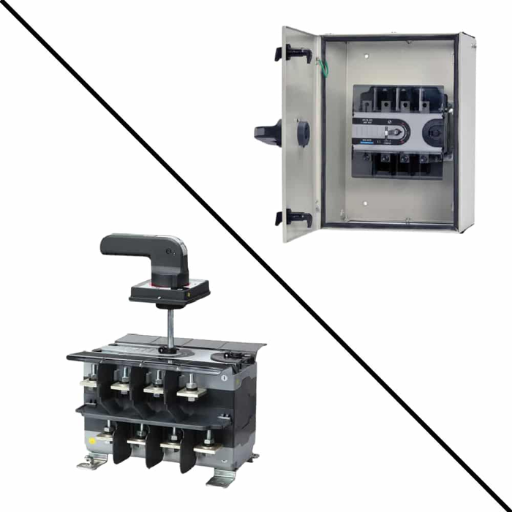
Transfer Switch Breaker Failures:
Automatic transfer switch systems contain breakers which can operate without displaying any signs of operational failure. The ATS system appears to transfer operations when its switch mechanism works but the critical load remains disconnected because its breaker stays open. The transfer switch position indicator shows “Generator,” but the critical load has no power.
Pre-Transfer Testing Recommendations
Breaker Testing as Part of Generator Commissioning:
The installation of a new standby generator system requires testing of all breakers located within the emergency power circuit. The complete system requires evaluation through infrared thermography tests which need to be conducted while the generator operates its full load. The technicians will conduct primary injection tests to evaluate each breaker’s ability to trip under various conditions. The team will conduct voltage drop tests which measure baseline voltage levels through each breaker. The team needs to confirm that generator breaker, ATS breakers, and load breakers exhibit proper selective coordination.
Maintenance Schedules for Generator-Fed Panels:
Facilities that operate at critical levels should establish scheduled times for testing their circuit breakers. The generator exercise cycle requires both visual inspection and thermal scan to be conducted every month. The emergency power path breakers will undergo functional testing which needs to be done every year. The critical circuits require testing through primary injection methods or breaker replacement every five years.
Documentation Requirements:
NFPA 110 (Standard for Emergency and Standby Power Systems) requires documented testing of emergency power systems. The documentation needs to include details about breaker condition which must show thermal imaging records and test results and replacement history.
When to Replace vs. When to Repair
Replacement Is Required When:
The system displays suspected internal mechanism failure The internal failure of a breaker shows through three signals which show high resistance and intermittent operation and unusual heating. The device requires complete replacement because circuit breakers cannot be repaired in the field. The internal components of the breaker need complete destruction for their examination and maintenance work.
All breakers which show burn marks and melted housing and deformed components need immediate replacement. These symptoms indicate the breaker has already experienced fault conditions or severe overheating. The internal components of the device remain intact but the device has suffered internal damage.
The equipment exceeds the maximum age limits established by the equipment manufacturer. Under normal operating conditions commercial-grade breakers are expected to function for 20 to 25 years. Breakers installed in extreme conditions which include high temperature and high humidity and dust and corrosive atmospheres need to be replaced before their scheduled time. All breakers which were built before 1990 need an evaluation for replacement based on their current status.
Power problems which occur repeatedly without explanation The breaker becomes the main suspect when a circuit experiences power interruptions that do not depend on wiring or loads. The process of replacement proves to be more economical than spending funds on complete diagnostic procedures while also removing a possible failure point.
Professional Assessment Recommended:
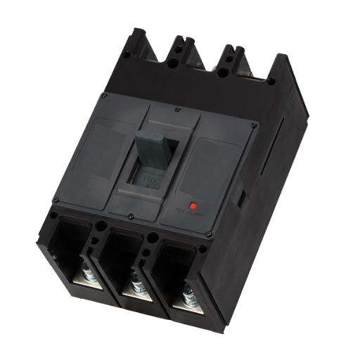
Three-Phase Systems:
The failure of three-phase breakers results in unbalanced load conditions which create voltage sags on non-failed phases and lead to equipment failures. Professional assessment ensures proper replacement breakers with correct interrupting ratings and trip characteristics.
Healthcare and Critical Facilities:
All hospitals and data centers plus similar facilities must operate without experiencing any unexpected power outages. The evaluation process ensures that breaker replacement maintains compliance with all relevant codes and standards while preventing any introduction of new risks.
Selective Coordination Requirements:
The requirement for selective coordination in systems requires engineering analysis before replacing breakers to ensure proper coordination between breakers and upstream equipment.
Preventing Silent Breaker Failures
Regular Inspection Schedules
Monthly Visual Checks for Critical Panels:
- The breaker faces need inspection to check for any signs of discoloration or damage.
- The presence of buzzing or humming sounds needs assessment during the equipment’s normal operation.
- The team needs to check whether all breakers on the bus have correct installation.
- The team needs to check any recent incidents of improper equipment operation.
Annual Professional Testing:
- The thermal imaging survey requires complete coverage of all panel areas.
- The team needs to tighten all connections until they reach the torque specifications established by the manufacturer.
- The team will conduct functional tests on all breakers that protect vital electrical circuits.
- The record needs to show all breaker ages together with their future replacement schedule.
Five-Year Major Maintenance:
- The team needs to evaluate whether they should replace breakers that have reached 20 years of service.
- The testing team will conduct primary injection tests on both main and critical branch breakers.
- The team will conduct thorough panel cleaning together with complete equipment inspection.
- The team will create new single-line diagrams to show updated breaker schedules.
Proper Loading Practices
The process of continuous operation above 80% rating for electrical breakers causes their thermal aging to proceed at an increased rate. Breakers need to be installed according to their actual weight capacities which should be divided between various circuit breakers who will operate under extreme load conditions.
Breaker contacts experience stress from motor starting currents which range from 5 to 7 times the normal operating current. Where frequent motor starting occurs, consider:
- Upsizing breakers appropriately for motor starting
- Using magnetic-only motor circuit protectors
- Installing soft starters or variable frequency drives to reduce inrush
Understanding Derating Factors:
The rating system for breakers operates under the assumption that specific ambient temperature conditions will exist which usually maintains a 40°C threshold. Breakers need to be derated when installed in hot environments or when their panels receive direct sunlight or when their enclosures have inadequate air circulation. Consult manufacturer documentation for specific derating curves.
Conclusion: Protecting Your Power Infrastructure
Circuit breakers can and do fail without tripping. Internal contact corrosion, bimetallic strip fatigue, and mechanical linkage wear can all render a breaker incapable of providing protection while the external handle remains firmly in the ON position. The electrical systems which power every building from residential homes to essential industrial facilities face hidden dangers from these failures which operate without producing any sound.
Key takeaways for maintaining reliable protection:
- Recognize the symptoms: Intermittent power along with voltage drop under load and unusual heating and physical indicators which include burn marks and buzzing sounds all indicate potential breaker degradation.
- The testing procedures must be implemented through three specific methods which include visual inspection and voltage drop testing and thermal imaging to discover failing breakers before they lead to outages and safety hazards.
- The generator angle needs to be evaluated because silent breaker failures represent a major issue for facilities which use standby power since these failures stop emergency power from reaching vital equipment.
- The replacement of circuit breakers should be done because these devices cannot be fixed through repairs. The only safe way to handle a suspected failure is through replacement.
- The preventive maintenance schedule needs to be followed because regular inspection and testing procedures discover problems at an early stage which prevents unplanned outages and safety incidents.
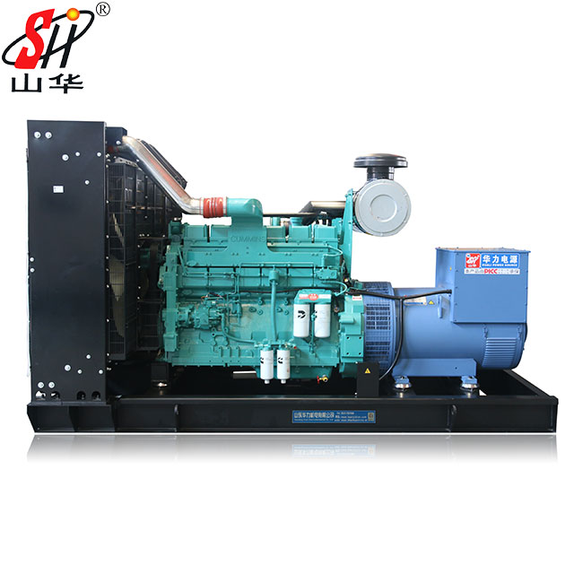
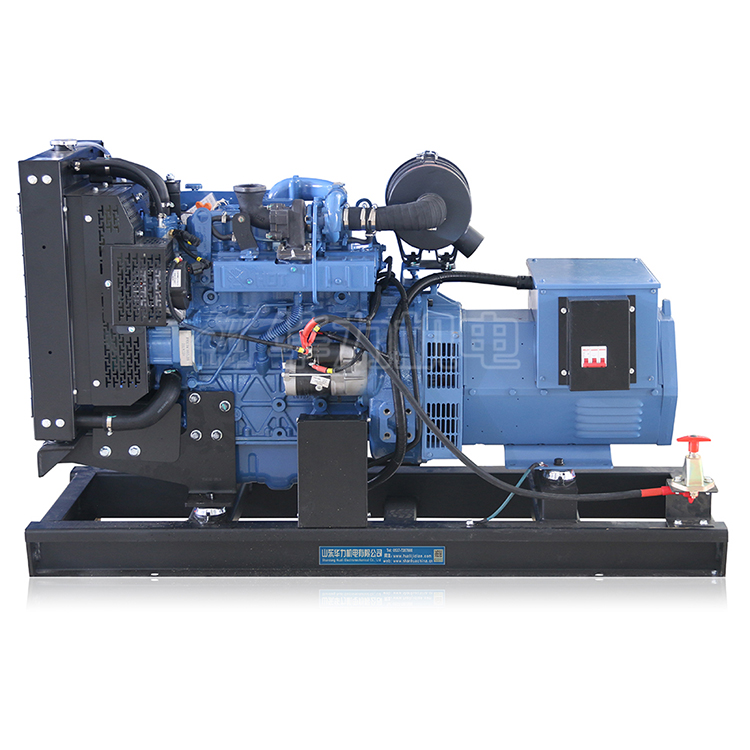
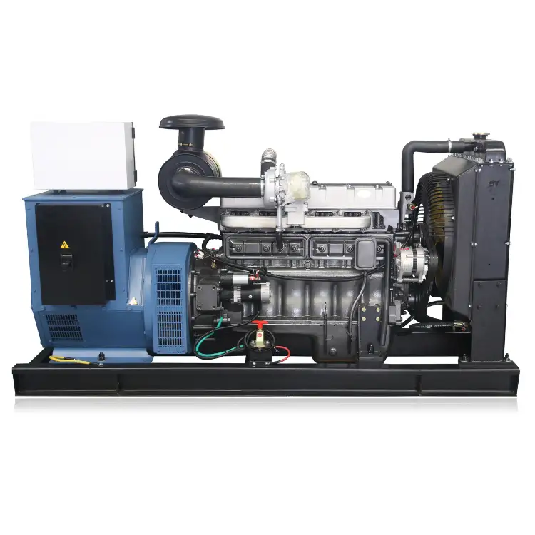
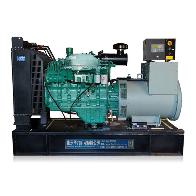
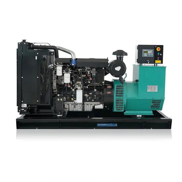
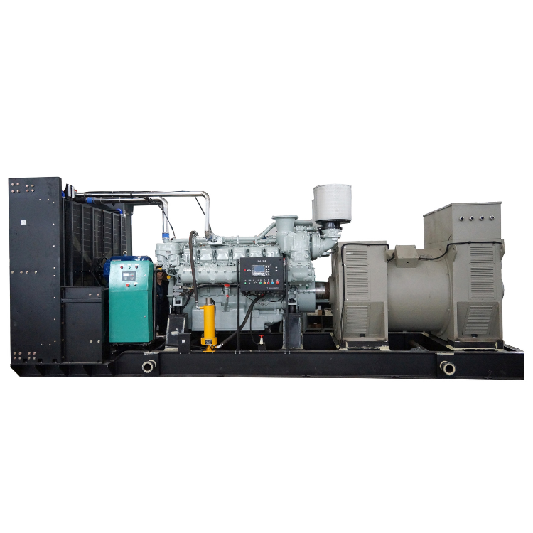
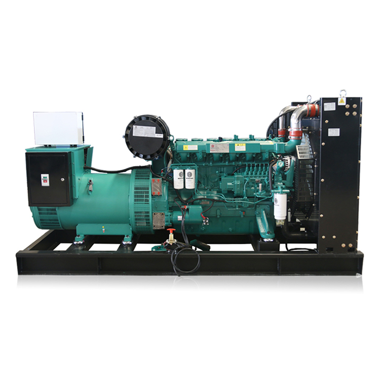
Shandong Huali Electromechanical Co. Ltd. provides reliable power protection which covers all components between the generator set and the electrical system. Our ISO9001-certified manufacturing and national standard testing centre ensure that the generator sets we deliver provide the dependable backup power your operations require. Your critical operations will achieve power reliability through proper maintenance of distribution equipment which includes circuit breakers.