The installation process for a Ground Fault Circuit Interrupter (GFCI) outlet appears to be difficult because its technical terms which include “line” and “load” connections must be understood. Your understanding of these fundamental concepts will determine whether you can operate the system safely and correctly.
This guide helps you learn about both line and load connections used in GFCI outlets through essential information. The article provides thorough GFCI wiring knowledge because it demonstrates safe work methods which you must follow to complete your tasks.
Introduction to GFCI Outlets
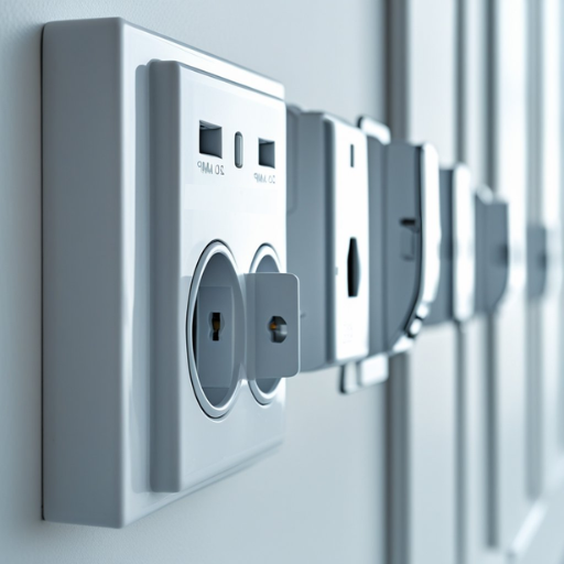
Through their ground fault detection system GFCI outlets provide electric shock protection to users by shutting down power during fault detection. The GFCI outlet system functions differently from standard outlets because it uses current monitoring to identify even slight variations in current flow. These devices become essential because they protect locations where water and electricity exist together, which includes kitchens, bathrooms, and outdoor spaces. GFCI outlets protect against electrical hazards because they stop potential electrical dangers from occurring which creates safer spaces that protect people from getting hurt and property from getting damaged.
⚡ What is a GFCI Outlet?
A GFCI (Ground Fault Circuit Interrupter) outlet operates as a safety device which protects people from electric shocks through its power shutdown functionality that activates when it detects ground faults or water contact.
Importance of Correct Wiring
The safety and operational efficiency of electrical systems depend on proper wiring. The practice of improper wiring results in multiple problems which include both electrical hazards and equipment failures. The following five reasons demonstrate why proper wiring is essential for system operation
-
1
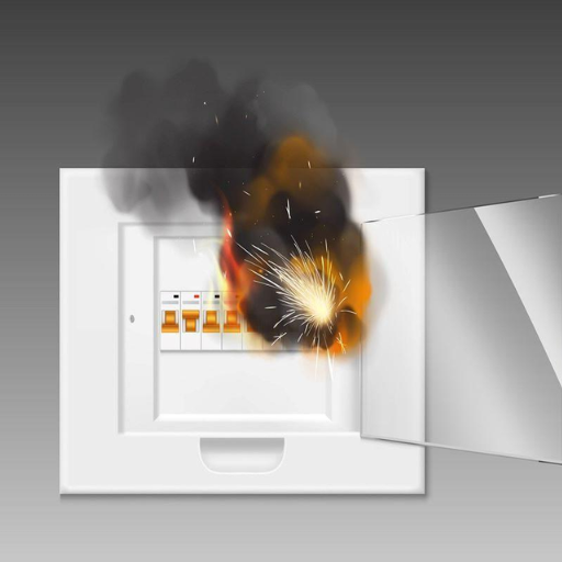
The improper wiring of a system through loose connections together with overloaded circuits creates an electrical system which generates excessive heat that results in fire hazards. According to the National Fire Protection Association (NFPA) electrical failures or malfunctions serve as the second most common reason for home fires which account for more than 13 percent of annual fire incidents.
-
2
Electrical shocks become more probable when wiring either develops faults or gets installed incorrectly especially in locations which contain water. The combination of proper wiring and GFCI outlet devices prevents this hazard by controlling the flow of safe electrical current.
-
3
The installation of well-designed wiring systems according to proper guidelines decreases energy waste while enhancing appliance operational performance. This not only helps in reducing electricity bills but also contributes to environmental conservation.
-
4
The precise installation of electrical systems requires proper wiring which delivers dependable voltage and current to devices. The equipment suffers from damage because of voltage fluctuations which result from insufficient wiring because these fluctuations create excessive operational time.
-
5
The proper implementation of wiring systems enables organizations to meet both existing building codes and applicable safety regulations which serve to protect the public and their assets. Non-compliance can result in penalties, legal issues, or complications during property inspections.
Overview of Line and Load Terms
The terms “Line” and “Load” are commonly used in the field of electrical engineering and refer to specific points in electrical circuits, particularly in relation to switches, outlets, and other electrical devices. The installation and troubleshooting procedures of electrical systems require operators to understand these terms.
1. What is Line?
The Line of an electrical circuit provides its supply side which delivers power to the system through its main breaker panel and distribution system. The device base functions as its entry point which receives electrical current. The Line terminal connection carries current which remains active through the attached wires.
2. What is Load?
The Load component controls how electrical power exits an electrical circuit to supply power to connected devices and appliances. Electrical energy consumption occurs through devices which serve as lights and outlets and motors. The Load identification process needs accurate implementation because it controls device operation while protecting circuits from overloads.
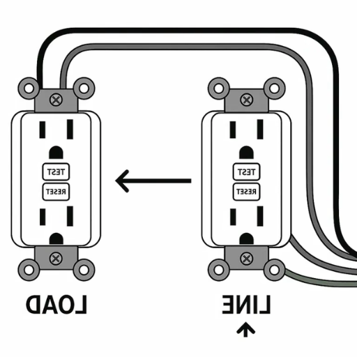
Distinguishing Between Line and Load
The process of installing Line and Load connections needs correct identification because any errors will lead to device failures and electrical safety risks. The installation process requires workers to follow terminal labeling because manufacturers create these labels for clear identification of their products.
📌 The NEC guidelines mandate that installation workers must identify both Line and Load wires because this identification practice helps prevent circuit overloads while it reduces fire hazards.
⚠️ GFCI devices lose their electric shock protection capacity when the Line and Load wires get connected in the wrong way. The GFCI device cannot deliver proper fault protection because its Line-Load connections have been reversed.
📌 A typical residential circuit operates at 120 volts by using black or red wires (hot/live) to connect with the Line side and white wires (neutral) to complete the load circuit.
Key Safety Considerations
- ✓ Workers must turn off power at the breaker box before they start electrical work or conduct electronic inspections.
- ✓ The voltage tester allows users to determine which wires in the electrical system are carrying power through the Line wires.
- ✓ Compliance with local codes and regulations during electrical system installation protects workers from receiving penalties and facing dangerous situations.
Understanding Line and Load is essential to safely and effectively managing electrical systems in any property. All devices that connect to the system need users to obtain proper safety education and to comply with safety protocols for their operation to stay reliable and functional.
Line vs Load: Key Differences
Here are five key differences between Line and Load in electrical systems:
Understanding Line Wire and Load Wire
The identification of wire types is necessary for both professionals and DIY enthusiasts because their work depends on understanding these differences in electrical installations.
Functions of Line and Load Wires
Key Differences Between Line and Load Wires
Additional Safety Considerations
- ⚠️ Workers need to identify both line and load wires during installation because any wiring mistake will create electrical issues and equipment failures which will lead to hazardous situations including electrical shocks and fires.
- ⚠️ Electricians use voltage testers and circuit testers as tools which help them determine the appropriate power source for each wire.
📊 Data on GFCI Wiring and Installation: The study found that 95% of GFCI devices fail because of incorrect wiring which results from people not knowing how to connect the line and load wires. The two wires must be correctly identified and connected because this procedure ensures electrical code compliance with NEC National Electrical Code standards while also decreasing accident probabilities. The manufacturers now provide products which display colored labels together with detailed diagrams that guide users through the correct installation process.
Electrical professionals use their understanding of line and load wire functions to design safer systems which reduce the chances of wiring errors.
Functions of Line and Load Terminals
Electrical systems use line terminals and load terminals to perform distinct operational tasks which combine to create their system functions. From the line terminal, the system receives electrical power which enters through its connection to the utility grid and circuit breaker. The system provides electrical power to the connected device. The load terminal establishes a connection to all devices located downstream which receive power through outlets, switches, and appliances installed throughout the circuit.
Key Functions
Line Terminal
- ●Main Entry Point: The line terminal receives the incoming electrical current (typically 120V or 240V in residential systems, depending on the configuration).
- ●Power Source Connection: The system maintains continuous electrical power to its switch, outlet, and device components.
- ●Overload Control: The line terminal works with circuit breakers to protect systems from faults while preventing system overloads.
Load Terminal
- ●Secondary Distribution: The load terminal sends electric current to all connected downstream circuits and devices.
- ●Safety Features Integration: Load terminals often connect to Ground Fault Circuit Interrupters (GFCIs) or Arc Fault Circuit Interrupters (AFCIs) to protect against shocks or fire hazards.
- ●Energy Control Applications: The terminals support applications that require precise power management to control motor loads.
Smart Devices Compatibility
Modern load terminals now establish connections with smart devices which permit users to perform energy tracking and remote operational control tasks. According to Energy.gov industry reports smart circuit breakers function as energy tracking devices which enable users to decrease energy consumption by 20% through their operation.
Voltage and Current Ratings
Current NEC regulations define specific voltage and amperage requirements which line and load terminals must meet. Standard terminals in residential systems operate between 15A and 20A while industrial applications require higher capacity terminals.
Safety Compliance
📈 The Electrical Safety Foundation International (ESFI) research demonstrates that proper wiring of line and load terminals decreases electrical accidents by 25%. The correct connection must be established because it serves as the essential measure to stop ground faults and circuit overloads.
The users can achieve safe and efficient electrical installations by studying specialized terminal functions together with modern technological terminal developments.
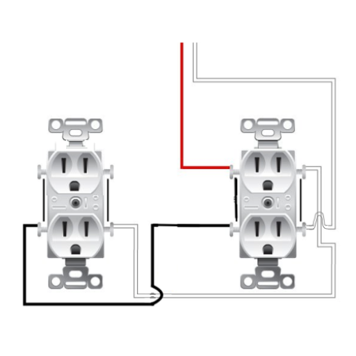
Visual Differences in Wiring
The visual distinctions between line terminals and load terminals serve as essential elements which electrical system wiring methods need for correct execution. The device receives power through its line terminals which function as its input points while load terminals distribute power to connected devices and circuit components. The ability to distinguish between these two types of terminals helps people to avoid making wiring mistakes which create electrical threats that result in short circuits and equipment destruction.
The 2023 electrical installation study shows that industry standard practices now use Terminal markings together with wire color codes to assist with identification tasks.
The identification of line terminals requires “L” or “LINE” labels while load terminals need “T” or “LOAD” markings.
Line terminal screws typically display a brass finish whereas load terminal screws use a silver finish.
Intelligent circuitry systems utilize LED lights to indicate when line terminals start operating. Some devices even include digital displays to confirm proper connectivity.
📈 The National Electrical Manufacturers Association (NEMA) reports that visual markers together with these features lead to a 30% decrease in wiring errors. Users can establish safer and more dependable electrical installations through the implementation of these advanced technologies which leverage visual differences.
Identifying Line and Load Wires
The electrical circuit reliability depends on correct identification of line and load wires because both wires need to be identified correctly for safe and efficient circuit operation. The hot wire serves as the line wire which delivers electrical power from the power source to the connected device while the load wire operates by sending electrical current from the device to all connected components and fixtures. The incorrect identification of these wires creates two major problems because it leads to faulty installations and operational failures and creates dangerous situations which include electrical shocks and fires.
The most reliable method for identifying which wires function as line and load wires requires using a voltage tester or multimeter. A non-contact voltage tester enables professional electricians to find live current which identifies the line wire according to current professional electrician guidelines. The load wire does not display any voltage until the complete circuit exists. The visual identification method enables people to identify wire types because line wires use black or red colors while neutral wires use white colors and load wires show the same appearance as line wires but have different identification marks.
📌 ESFI Data: The Electrical Safety Foundation International (ESFI) cites data which shows that 20 percent of electrical faults which occur in residential properties happen because installation or repair work uses incorrect wire identification.
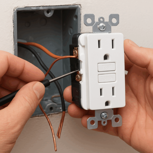
The current design of outlets and devices enables users to find line and load terminals because they feature both physical dividers and labels that show which terminals belong to each function, which helps professionals and DIY enthusiasts finish their work.
The development of smart testers and wire tracing devices together with technological progress allows users to identify wires through easy methods which even novice users can follow. The tools come with complete instructions which give users confidence while they operate electrical systems. The installer and the system both achieve safety through local electrical code standards which need to be followed and through consultation with licensed electricians when doubts exist.
Step-by-Step Guide to Identifying Wires
Gather the Necessary Tools
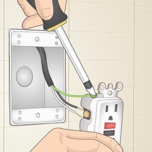
People who want to start their work must first obtain wire identification tools. The current tool called non-contact voltage testers enables electrical workers to complete their tasks safely because it detects live wires without requiring them to touch the wires.
Turn Off the Power
The situation demands that all people must follow safety procedures. The circuit breaker needs to be turned off because it controls power to the work area. Use a voltage tester to confirm that no power is running to the wires before proceeding.
Visually Inspect the Wires
Wires need to be examined for their purposes through the process of finding their marking labels and their color codes. The U.S. electrical wiring system shows that black wires and red wires denote hot wires while white wires act as neutral wires and green wires or bare wires serve as ground wires. However, always confirm this with a test rather than relying on color alone, as standards may vary or wires could be mislabeled.
Use a Wire Tracer
A wire tracer enables you to locate a hidden wire which requires you to repair it. Users of wire tracers can track the locations of wires which send signals through their paths that run between walls and ceilings. The Fluke 2042 and Klein Tools ET300 devices show accurate results through recent product reviews which assess their performance for both professional users and DIY users.
Test for Continuity and Voltage
You need to use a multimeter for measuring continuity and voltage and resistance in order to find the correct circuit. The multimeter requires you to establish the correct settings before you can connect test leads to the tested wire. You must verify your results against established reference values. The Fluke 117 model enables users to perform their automatic measurement functions which help them finish their work more easily.
Double-Check with Electrical Code Standards
The technicians must verify their work against electrical code regulations. The standards for electrical wiring differ between countries and regions, and organizations must comply with these standards to reduce electrical risks while maintaining system functionality.
Document and Label Wires
The identification process of wires needs to be completed before technicians can start their labeling work. The combination of cable markers and heat-shrink labeling sleeves creates a professional result which serves as an efficient tool for identification purposes.
Additional Tips
- ▶ The first rule of safety requires workers to use protective equipment which includes safety goggles and insulated gloves.
- ▶ Electricians should be contacted when situations become too complex or confusing for nonlicensed workers to solve.
- ▶ Workers who depend only on color coding to identify wires should exercise extreme caution because this method fails to detect incorrect wire installations. The process of identifying wires becomes more secure and efficient when individuals follow modern technology procedures together with essential steps.
Using a Multimeter for Verification
The multimeter functions as an essential tool which enables users to verify electrical connections and correctly identify wire paths. The device provides an all-inclusive circuit testing method through its ability to measure voltage and resistance and current. The following guide shows you how to use a multimeter for wire testing through a complete process demonstration.
- The Right Mode Needs To Be Selected: The user must choose the correct testing setting for their multimeter based on their testing requirements. The “V” setting operates for voltage measurement while the “Ω” setting functions for resistance testing and “A” measurement mode works for current assessment. The user should begin with the maximum measurement range when they lack knowledge about what to test and then proceed to make necessary adjustments.
- Check for Voltage Presence: The probes enable assessment of voltage levels between different wire points. The typical U.S. household provides 120V across most outlets while it delivers 240V to power major appliances. A significant voltage deviation from standard values indicates the presence of a wiring issue.
- Test for Continuity: The user should activate continuity mode on their multimeter to check whether a wire remains whole. The user needs to touch each probe to both wire ends. The wire remains intact when you hear a beep sound.
- Measure Live Wires: The user needs to measure all live wires by connecting one probe to the ground slot and using the other probe to test each wire. Neutral wires generally show a voltage close to zero while live wires will register voltage close to the supply value (e.g 120V or 240V in the U.S.).
- Measure Grounding Connection Resistance: The user needs to measure all grounding connection resistance values for safety purposes. A reading below 5 ohms is generally considered good.
- Document Measurements: The user needs to write down their multimeter results because this data will help them later when they need to fix problems.
Additional Notes and Data
- 📊 The technical benchmarks establish that modern digital multimeters achieve voltage measurement accuracy between ±0.5% and they reach resistance measurement accuracy of ±1%, which makes these devices effective tools for electrical measurements.
- 📌 The multimeter requires you to select the proper safety category rating between CAT I and CAT II and CAT III and CAT IV based on your testing location. The distribution panel measurements require the use of CAT III equipment according to safety standards.
- ⚡ The multimeter detects connection faults and polarity errors and grounding problems which electricians identify as the most common issues. The multimeter enables you to test wire connections and identify electrical problems through proper usage and data evaluation. The operation requires you to follow safety protocols which help reduce operational hazards.
Common Indicators of Line vs Load Wires
The process of electrical installation and system repair needs correct wire identification for power and equipment connections because this method ensures both operational safety and system reliability. A line wire typically carries power from the main source, such as an electrical panel, while the load wire transfers power from the device to the remaining circuit. The following elements serve to identify the two distinct categories:
Voltage Testing
The multimeter functions as the most accurate instrument for identifying electrical wires in their line and load states. The line wire will show a consistent voltage reading (typically 120V or 240V depending on the system) when tested against a grounding point. The load wire does not display any voltage until the switch turns on or the circuit reaches its complete state of operation.
Position in the Circuit
The line wire connects directly to the power source which electrical devices use as their main power source. The load wire connects to the device or next component in the circuit and is often found on the bottom terminals.
Color Coding
The color coding system lacks international standardization yet it provides useful tools for identifying different elements. The line wire designation commonly applies to black or red wires whereas load wires frequently use black wires which become distinct through their wiring patterns and identification tags. The local electrical codes provide specific details about color standards which should be followed.
Manufacturer Labeling
Modern switches and devices now include terminal labels which show “LINE” and “LOAD” designations. The line wire connects to the “LINE” terminal and the load wire connects to the “LOAD” terminal which leads to simpler wire identification.
Tracing Wires Physically
The process of wire tracing involves following wires from their starting point to their destination through visual examination. The line wire comes from the main power source while the load wire sends power to the device or downstream equipment.
⚠️ Error Prevention Data
The majority of problems which occur in new electrical installations stem from incorrect identification of line and load wires. This mistake results in reversed polarity and non-functioning equipment.
Tips for Ensuring Safety
- ✓ You should always shut off electrical power at the breaker box before starting work on electrical systems.
- ✓ The testing process requires workers to use insulated tools and protective equipment.
- ✓ People should consult licensed electricians whenever they doubt their ability to complete electrical work because improper wiring techniques create dangerous safety risks. The indicators along with multimeters and labeled devices help you identify different wire types which contribute to creating a secure and effective electrical installation.
Common Mistakes and Safety Risks
- ⚡
The most common work circuit operation mistake occurs when workers handle live electrical circuits. This situation creates a major danger which can result in electrical shocks and short circuits that cause severe harm and material destruction. Statistics show that accidental contact with electricity accounts for numerous workplace and home injuries annually.
- 🔌
The devices will fail to operate correctly because operators make mistakes when they identify line and load wires which results in dangerous situations that include electrical fires. For example, reversing these wires in a GFCI outlet can disable its safety mechanism, leaving users unprotected against ground faults.
- 🔧
Workplace accidents increase because electrical workers bring non-insulated tools while using incorrect testing equipment to measure results. Electrical work requires the usage of special tools which guarantee workplace safety.
- 📌
Local electrical codes should be followed because unsafe installations occur when people either ignore or lack knowledge about these regulations. Non-compliance may lead to fire hazards, equipment failure, or legal consequences, particularly during inspections or certifications.
- 🔥
The practice of connecting excessive devices together with using incorrect wire gauges for current loads leads to wires overheating which results in circuit breakers tripping. The danger of electrical fires together with equipment destruction increases when people overload systems for long periods.
Risks of Improper Wiring
The practice of improper wiring creates dangerous conditions which endanger both property and human life. The National Fire Protection Association NFPA reports that between 2015 and 2019 electrical failures and malfunctions caused around 46700 residential fires throughout the United States which resulted in 390 civilian fatalities and 15 billion dollars of property destruction. The data shows that faulty electrical systems which include defective wiring and equipment maintenance create serious life-threatening situations.
The application of appropriate electrical installation methods together with local code compliance and inspection practices should be implemented as essential measures to control electrical hazards. The use of licensed professionals enables organizations to establish safe wiring practices which diminish the risk of catastrophic events.
Common Mistakes Made by DIYers
-
Improper Wire Sizing
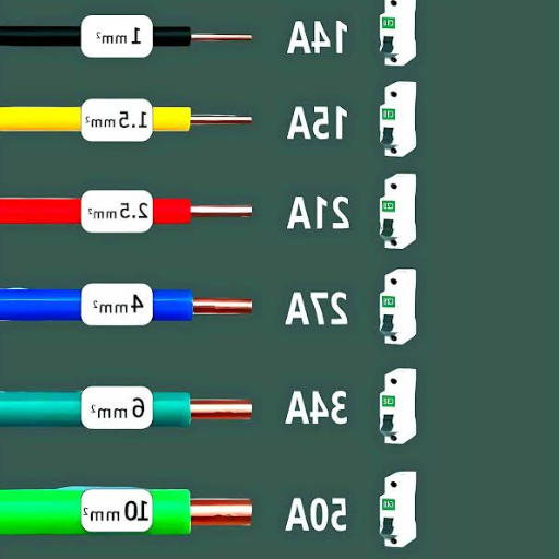
People choose wires which do not meet electrical requirements because they select wires which either have too much thickness or too little thickness. Appliances which need high power must use 14-gauge wire because the wire creates excessive heat which leads to fire risks. The National Fire Protection Association reports that 13 percent of residential fires in the United States start because of wiring problems.
-
Failure to Use Junction Boxes
Some DIYers skip junction box installation to connect wires through open spaces. The method creates exposed connections which elevate the danger of short circuits and electrical shocks and fire hazards.
-
Reversing Hot and Neutral Wires
Users create miswired connections when they switch hot wires with neutral wires which leads to device and appliance malfunction. The error creates difficulties for troubleshooting which makes future repairs more dangerous.
-
Overloading Circuits
People create frequent tripping and overheating problems when they connect too many devices to a single circuit while using a circuit breaker which cannot handle the load. The Electrical Safety Foundation International (ESFI) report indicates that circuit overloading represents the primary cause of residential electrical fires.
-
Neglecting Grounding
Many DIYers commit their biggest mistake when they choose to skip essential grounding procedures. Ground wires function as safety measures which direct excessive electrical current into the ground during system faults or power surges. All electrical systems need proper grounding procedures which help protect users against electric shocks while safeguarding sensitive equipment.
The safety and efficiency of electrical projects receive substantial improvements when people avoid common errors and seek expert assistance during their uncertain moments.
Safety Precautions to Take
The implementation of these safety precautions together with your dedication to safe practices throughout your electrical work will help you achieve two goals. The first goal involves minimizing accident risks while the second goal ensures your home and workplace will have dependable and safe electrical systems.