The selection of wire size for electrical systems has vital importance because it determines both safety measures and energy efficiency and building code compliance. The process of selecting wire size and gauge specifications becomes essential for circuits that need to handle a 40-amp load. The use of incorrect wire results in overheating and equipment damage which creates fire hazards. The blog post provides a comprehensive exploration of wire sizing requirements which specifically apply to circuits with 40 amp ratings. The guide will teach you how to select appropriate wire size while explaining gauge functions in electrical circuits and which standards must be met to achieve safe operational requirements.
Introduction to Wire Size for 40 Amp Circuits
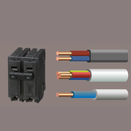
For a 40 amp circuit the required wire size needs to be 8 AWG American Wire Gauge. The wire maintains safe current handling capacity because its dimensions protect against overheating. Copper wire must be used as the standard material unless your circuit requirements or local electrical codes permit the use of aluminum which needs bigger wire size to match its reduced conductivity. The regulations exist to maintain safety standards because local electrical codes and standards must be followed for this purpose.
Importance of Correct Wire Size for Safety
The system needs correct wire selection because this choice protects its electrical components during all operational times. When wires are selected with improper dimensions multiple dangerous situations emerge which lead to operational difficulties and equipment breakdowns. The correct wire size must be chosen because it serves five essential purposes.
Preventing Overheating
Electrical currents create excessive heat because undersized wires lack capacity to handle their designated loads. Insulation breakdown and short circuit initiation and fire ignition represent three dangerous outcomes which result from overheating conditions. High-load appliances such as air conditioners and dryers need specific ampacity standards which protect users from hazardous situations.
Ensuring Voltage Drop is Within Safe Limits
A wire that is too thin for the circuit’s load may experience significant voltage drops which reduce the efficiency of connected devices. The voltage drop threshold of 5% leads to motor and light and electronic device performance issues which exist until they stop functioning.
Enhancing Energy Efficiency
Proper wire sizing ensures energy losses stay at minimal levels. The use of larger wires in systems with high power demand leads to decreased resistance which results in better energy conservation and reduced operational expenses.
Compliance With Electrical Codes
The security requirements which determine the correct wire sizes for installation purposes are established by local and national electrical code standards. Residential and commercial environments face safety hazards because non-compliance leads to fines and insurance issues and dangerous situations.
Supporting Long-Term Reliability
The use of correctly sized wires provides stable performance which lasts for extended periods while minimizing the chance of failures. The electrical systems in industrial facilities need larger wire sizes because their circuits extend over long distances.
The selection of wire sizes needs to be based on three factors which include the circuit’s intended load, wire material, and environmental factors to achieve better safety and efficiency and operational longevity.
Overview of Electrical Code Compliance
Electrical systems in residential and commercial and industrial spaces need to follow electrical codes which ensure both safe and efficient system operation. The National Electrical Code (NEC) sets electrical standards which organizations must implement to safeguard their facilities against electrical fires and shocks and equipment destruction. The codes establish precise installation requirements which include specifications for wiring techniques and grounding methods and circuit protection systems and energy efficiency standards.
NEC Article 310 defines all conductor specifications which include general wiring requirements and their corresponding ampacity values established through different temperature ratings and insulation types. The standards enable safe wire operation by ensuring wires remain within their load capacity during usage.
Electrical codes need regular updates because new technologies emerge and safety standards undergo modifications. The NEC 2023 edition establishes new rules which control renewable energy sources and electric vehicle charging stations and energy storage solutions that became vital in modern power systems.
The strict code compliance process enhances operational safety and reliability while improving inspection efficiency and reducing potential legal and financial risks. The solution for effective compliance needs certified professionals to handle installation and upgrade tasks.
Wire Gauge Requirements for a 40 Amp Circuit
The selection of the appropriate wire gauge must be executed to achieve safety and operational efficiency while meeting NEC (National Electric Code) standards for 40 amp circuits. The standard requirement for a 40 amp circuit establishes that 8 AWG (American Wire Gauge) copper wire needs to be used or 6 AWG aluminum wire should be applied under standard conditions. The actual current carrying ability of the wire needs to be assessed after evaluating both wire length and temperature conditions in the following way.
Key Details and Data
🔵 Copper Wire for 40 Amps
- Standard Recommendation: 8 AWG
- The maximum safe distance for voltage drop to remain below 3% at 120V/240V reaches approximately 50 to 70 feet.
- The system serves electric stoves and ovens together with air conditioning units as its primary application.
🔴 Aluminum Wire for 40 Amps
- Standard Recommendation: 6 AWG
- The lower conductivity of aluminum wire requires that it be installed with a wire gauge which exceeds the requirements for copper wire.
- Applications include areas where aluminum wiring can be used which includes specific residential and commercial spaces.
📏 Voltage Drop Evaluation
The power delivery system needs to upgrade wire size to 6 AWG copper for runs longer than 50–70 feet to maintain voltage levels and provide reliable power distribution.
🌡️ Temperature Rating
- 60°C Conductors: 8 AWG copper supports 40 amps.
- THHN/THWN wire types support 75°C or 90°C conductors which enable higher ampacities yet the circuit operates at the lowest-rated component.
📜 NEC Compliance
The NEC mandates adherence to proper wire sizing based on the application, insulation type, and environmental conditions. The most recent NEC edition needs to be consulted together with certified professionals to confirm that your circuit meets local code requirements.
The use of correct wire gauge prevents three disastrous outcomes which include overheating and energy loss and what could lead to fire hazards. In cases where your application encounters special temperature or distance requirements, you need to increase wire size to ensure safe operation and consult an expert for accurate calculations.
Standard Wire Gauge (AWG) for 40 Amp Circuits
When determining the appropriate wire gauge (AWG) for a 40 amp circuit, it is essential to follow the National Electrical Code (NEC) recommendations as well as consider specific variables like wire length, insulation type, and ambient temperature. The standard 40 amp circuit requires 8 AWG copper wire as its most common wire size.
Wire Material
- Under normal conditions, 8 AWG copper wire can safely carry 40 amps.
- Residential customers less frequently use aluminum wire, which needs 6 AWG to handle 40 amps because of its lower conductivity than copper.
Temperature Rating
Wire insulation ratings determine how much current a wire can carry. For example:
- The standard for typical conditions defines 60°C (140°F) rated cable as the base point for ampacity calculations.
- Cables rated at 75°C (167°F) or 90°C (194°F) will permit different ampacity levels, which must match the manufacturer-approved equipment specifications.
Wire Length
Voltage drop problems occur when wire lengths exceed 100 feet. To maintain operational efficiency and safety, the system requires 6 AWG copper wire as the necessary wire size.
Specialized Application Factors
Outdoor circuits, as well as circuits that operate at a higher temperature than normal, need their wire size to be increased to elevate its thermal efficiency.
Quick Reference Table for 40 Amp Circuits
| Wire Material | Standard AWG | Voltage Drop Adjustment | Temperature Rating Impact |
|---|---|---|---|
| Copper | 8 AWG | 6 AWG for long runs | Confirm with insulation type |
| Aluminum | 6 AWG | 4 AWG for long runs | Confirm with insulation type |
You should always check these recommendations against the most recent NEC codes and local laws. The project needs a licensed electrician who will handle special applications and uncertain condition situations to guarantee all safety standards are successfully met. The correct wire size protects against overheating hazards and fire dangers while maintaining energy efficiency.
Copper vs. Aluminum Wiring Requirements
The performance evaluation of copper and aluminum wiring systems needs to be conducted by users because both materials provide different advantages that match specific usage scenarios. The materials possess different benefits which make them suitable for specific applications.
- Conductivity and Performance
The electrical conductivity of copper establishes its status as the most efficient electrical conductor. The material enables electrical flow to pass through it with diminished resistance when compared to aluminum. Copper possesses greater tensile strength than other metals which enables it to withstand stretching and permanent deformation. Copper wires require less space than aluminum wires to transmit the same amount of electricity which makes them more practical for use in compact areas of residential and industrial buildings.
- Cost and Affordability
Large projects that focus on material costs find aluminum to be a better choice because it costs less than copper. The cost of aluminum wiring becomes 40 to 50 percent lower than the price of copper wiring when both systems have the same capacity to carry electrical loads according to market conditions. The initial expense appears lower, but extended maintenance and replacement costs occur because aluminum wiring needs special procedures for safe operation.
- Weight Considerations
The weight of aluminum serves as its main advantage for users. The weight reduction of aluminum to 50 percent compared to copper makes it easier to handle and cheaper to transport while reducing the weight load on structural elements needed for big projects. This property makes aluminum wiring a common choice for overhead power lines and high-tension cables.
- Corrosion and Stability
The superior corrosion resistance of copper compared to aluminum allows copper to withstand severe environmental conditions for extended periods. The older types of aluminum wires exhibit oxidation and expansion when they come into contact with moisture and air. The situation becomes dangerous because it results in loose connections which create higher fire hazards when proper management fails to occur. The combination of modern aluminum alloys and protective coatings has achieved better results than before but proper installation techniques and maintenance work are still essential for success.
- Sizing Requirements
The ampacity of aluminum wiring needs a wire gauge that exceeds copper requirements by two sizes. A 100-amp service needs #4 AWG copper wire or #2 AWG aluminum wire according to standard requirements. The requirement for higher gauge wire results in increased expenses for both conduit space and installation work. The National Electrical Code (NEC) guidelines which have been updated specify that the correct material sizing and insulation selection should be used according to different application requirements.
Common Applications
| Material | Typical Use | Pros | Cons |
|---|---|---|---|
| Copper | Homes, small appliances, HVAC systems | High conductivity, durability, smaller size | Higher material cost |
| Aluminum | High-voltage lines, large feeders | Lightweight, cost-effective for large installations | Larger size needed, more maintenance requirements |
The selection of wiring materials requires compliance with both the NEC codes and local regulations. The installation of aluminum wiring needs specific methods which require the use of anti-oxidant paste together with connectors that comply with aluminum standards. The best approach to maintain efficiency and safety for extended periods involves hiring a licensed electrician for assistance.
Using 8 AWG Wire for 40 Amp Applications
The evaluation of 8 AWG wire suitability for a 40-amp circuit requires assessment of three elements which include the insulation type and ambient temperature conditions and installation techniques. The National Electric Code (NEC) 310.16 states that 8 AWG copper wire with standard THHN/THWN insulation has an ampacity of 55 amps at 75°C which enables it to handle 40-amp circuits in most situations. The implementation of derating adjustments becomes essential when facing situations that require derating due to high temperatures or conduit fill requirements.
The use of aluminum wire results in decreased ampacity for electrical applications. The 8 AWG aluminum wire can handle 40 amps at 75°C which meets the minimum requirements for a 40-amp circuit. The installation of aluminum wiring requires special procedures which secure its proper function because oxidation will create overheating problems. The proper installation process requires usage of connectors which have been certified for aluminum use together with antioxidant paste to guarantee protection against future dangers.
The evaluation of voltage drop becomes essential for all situations which involve extended wire distances. The resistance of 8 AWG wire makes voltage drops become evident at distances beyond 100 feet which create performance issues for connected devices. The circuit length and load requirements can help determine whether wire upsizing to 6 AWG will effectively reduce the risk.
The NEC tables and guidelines together with local codes which establish higher safety requirements must be followed to maintain compliance and safety standards. The best method to verify your installation meets all regulations while working efficiently for extended periods is to hire a licensed electrician.
Factors Affecting Wire Size Selection
The selection process for the proper wire size in an electrical installation needs to assess multiple vital elements which will safeguard operations while meeting both safety requirements and efficiency standards and legal obligations.
Current Load (Amperage)
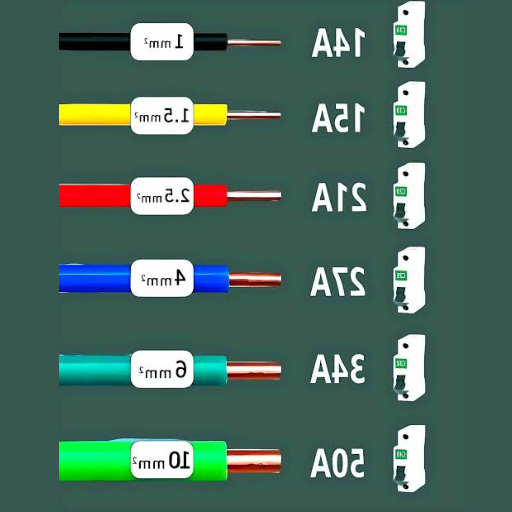
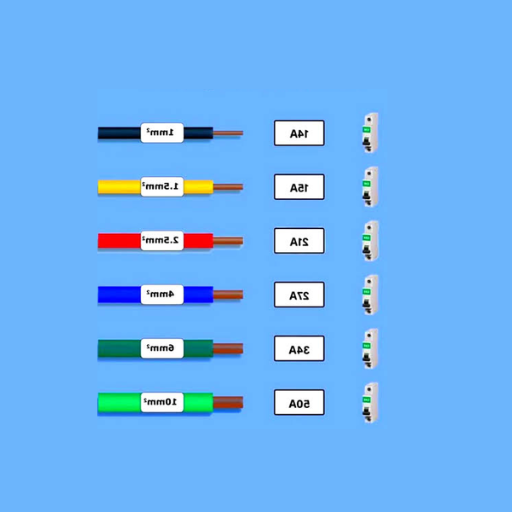
The circuit’s current capacity determines the required wire size. The wire thickness needs to increase for larger current loads because thinner wires will create overheating and fire risks. The 20-amp circuit needs 12 AWG wire as its standard requirement while 30-amp circuits generally require 10 AWG wire.
Voltage Drop
The wire length causes voltage drop because electrical current encounters resistance throughout its distance. The system needs voltage drop calculations for extended circuit runs because they affect device performance at connected points. The wire size needs to increase in this situation to decrease voltage drop problems.
Length of the Circuit
The total length of the wire from the power source to the farthest device is a key factor. The circuit needs larger gauge wires because longer distances create resistance which results in voltage drop that must be eliminated for proper system operation.
Ambient Temperature
The current-carrying capacity of electrical wiring depends on its surrounding temperature conditions. Higher temperatures in the environment decrease the safe current-carrying capacity of a wire. Thicker wires and heat-resistant materials need to be used in locations which experience high temperature conditions.
Conduit or Bundling
The wires which pass through a conduit or are bundled with other wires experience heat accumulation because they lack proper airflow. This situation requires a reduction in wire ampacity which might lead to the need for a larger wire size to safely transmit current under these circumstances.
The planning process for an electrical system requires analysis of all factors to achieve National Electrical Code (NEC) compliance and local regulation adherence which will ensure security and effective system performance.
Voltage Drop and Distance Considerations
The design process for electrical systems requires voltage drop assessment combined with power source distance evaluation because these two factors determine system performance and operational abilities of the system. Equipment becomes inefficient when voltage drops exceed acceptable limits which results in increased energy usage and represents a danger to sensitive equipment.
- Conductor Size: The distance increases, requiring electrical systems to use larger conductor sizes which helps reduce voltage drop. The use of smaller conductors results in excessive voltage loss which creates problems for power delivery to customers.
- Conductor Material: The most common conductor materials are copper and aluminum. Copper serves as the better conductor material because it delivers superior electrical conductivity to aluminum despite its higher cost.
- Current Load: The voltage drop increases when people transmit more electricity through a certain distance. The conductor size depends on accurate calculation of load current requirements.
- System Voltage: The higher voltage systems demonstrate reduced voltage drop which occurs when they transmit equivalent energy through long distances. The adoption of higher voltage systems leads to decreased demand for larger conductor sizes.
- Distance to Load: The physical distance from the power source to the load increases which results in higher voltage drop potential. The assessment of voltage drop requires accurate total wire length measurement because it needs to include both outgoing and return path wire lengths.
The system maintains NEC compliance because it needs to evaluate multiple factors which create specific adjustments that protect both operational efficiency and system performance reliability.
Common Use Cases for a 40 Amp Circuit
The 40 amp circuit provides power needs for both residential and commercial spaces which require dedicated circuits to support their higher electricity demands.
Electric Ranges and Ovens
The range of electric ranges and ovens power consumption spans from 8000 watts to 12000 watts based on their physical size and their operational capabilities. The power requirements of these devices can be safely supported through the installation of a 40 amp circuit. The installation of proper wiring and outlets is necessary to avoid overheating issues and breaker tripping problems.
Electric Water Heaters
Many electric water heaters need power circuits that deliver between 7500 watts and 10000 watts which corresponds with the requirements of a 40 amp breaker. The water heater needs all of its circuits to become dedicated to its operation so that it can function properly without interruptions.
Air Conditioners
The central air conditioning systems in residential buildings and small business facilities require a 40 amp circuit to power their compressors and fans which together use more than 9000 watts. The design process should include considerations for how seasonal usage patterns will affect system efficiency throughout the year.
Hot Tubs and Spas
Hot tubs and outdoor spas function between 7500 to 10000 watts depending on their heating systems and jet systems. GFCI protection must be implemented in wet areas to ensure safety through Ground Fault Circuit Interrupter systems.
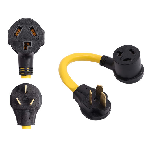
Large Electric Chargers for EVs
Level 2 EV chargers require a 40 amp circuit because their charging stations need 9600 watts to provide electric vehicles with effective charging. Dedicated circuit planning establishes dedicated electrical resources which will not interfere with any electrical systems that operate throughout the house.
The 40 amp circuit demonstrates its ability to handle high demand equipment which operates in different environments through these specific applications. Professional advice should always be sought for assistance.
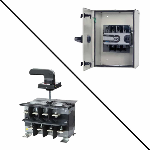
Breaker and Conduit Considerations
The proper installation of breakers and conduits needs to be evaluated before working on 40 amp circuits because this assessment protects both safety and code compliance. The selection of appropriate components ensures system safety while diminishing electrical system risks.
- Breaker Compatibility with Circuit Load: The breaker needs to be capable of handling the 40 amp circuit load according to its design specifications. The breaker function stops when an overload condition occurs because the device overheats until it reaches its trip point which creates dangerous conditions.
- Use of Proper Conduit Material: The installation environment determines whether the conduit needs PVC or metal as its appropriate material for construction. PVC materials are suitable for indoor applications whereas metal materials serve better for outdoor use because they provide long-lasting strength and protective capabilities.
- Wire Size for 40 Amp Circuits: The standard requirements for a 40 amp circuit wire installation demand the use of 8-gauge wire. The use of undersized wire results in overheating which creates a violation of local electrical codes.
- Breaker Type (Standard or GFCI): Most applications function properly with standard breakers yet kitchens garages and outdoor areas need Ground Fault Circuit Interrupter GFCI breakers to deliver better protection from electrical shocks.
- Conduit Capacity and Fill Limits: The conduit must not exceed its fill capacity because overcrowding wires within the conduit creates a risk of overheating. The National Electrical Code NEC conduit fill charts provide required information about fill limits which must be followed.
The implementation of these specifications enables you to establish a secure and effective 40 amp circuit system. The current local codes and the expertise of a qualified electrician need to be checked before making any decisions about this matter.
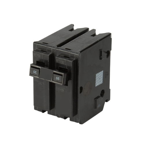
Choosing the Right 40 Amp Breaker
The electrical system requires a 40 amp breaker which ensures protection for people and equipment against potential hazards. The 40 amp breaker serves as the necessary power supply for electric water heaters and ovens and large air conditioners and specific machinery.
⚙️ Breaker Type
The single-pole breaker operates on 120 volts while the double-pole breaker powers heavy appliances using 240 volts. People use double-pole breakers to operate 40 amp circuits. The breaker needs to function with your existing electrical panel system. Square D and Siemens and Eaton and GE create breakers which function together but certain models do not work with each other.
🎯 Breaker’s Purpose
The 40 amp breaker must meet the requirements of the connected appliance. The total load needs calculation which shows whether the breaker matches the circuit requirements. The National Electrical Code (NEC) recommends that circuit loads should not exceed 80% of the breaker’s maximum capacity. The 40 amp breaker supports a continuous load which reaches 32 amps as its maximum limit.
📐 Wire Gauge Selection
The National Electrical Code (NEC) requires 40 amp breakers to use 8 AWG copper wire or 6 AWG aluminum wire according to its standards. The correct wire size needs to be selected because improper selection will lead to overheating and other dangerous situations.
🏆 High-Quality Materials
The breaker should fulfill all UL safety certification requirements. The modern circuit breakers feature thermal-magnetic trip systems which deliver organizations better protection against threats.
📜 Local Code Compliance
The selected breaker must comply with local electrical codes because different jurisdictions require additional standards that extend beyond NEC requirements.
🛡️ Additional Features
According to electrical circuit requirements you must search for breakers which come equipped with advanced safety features including AFCI and GFCI protection systems. The evaluation of these factors together with the implementation of current NEC standards allows you to select the appropriate 40 amp breaker for your needs. You need to obtain expert guidance from a licensed electrician for both component selection and installation process.
Conduit Sizing for Proper Installation
The correct size of conduit must meet established standards because it protects electrical systems from dangerous situations while delivering their intended performance. The National Electrical Code (NEC) establishes explicit rules for selecting appropriate conduit dimensions based on conductor count and conductor gauge and used conduit type.
Importance of Proper Conduit Sizing
- The practice of overcrowding wires inside conduits results in excessive heat accumulation which damages insulation and creates fire hazards.
- The process of correct sizing wire systems enables workers to easily pull and replace wires which decreases both labor expenses and installation time during maintenance activities.
Key Factors in Conduit Sizing
- Conduit Fill Percentage: According to NEC Chapter 9 Table 1 conduits should not exceed a maximum fill of 40 for systems with more than two conductors. This ensures enough space for heat dissipation and pulling conductors.
- Conductor Size and Insulation: The gauge AWG of the wires and type of insulation THHN NM etc. affect the total area the conductors occupy.
- Conduit Material: The same nominal conduit size results in various inner diameter measurements for PVC and EMT Electrical Metallic Tubing and RMC Rigid Metal Conduit which changes the number of wires that can be accommodated inside the conduit.
How to Calculate Conduit Size
- Step 1 – Calculate the total area of the conductors: The conductor dimensions that need to be used can be found in NEC Chapter 9 Table 5 or through manufacturer specifications.
- Step 2 – Determine the allowable conduit size: NEC Chapter 9 Table 4 provides information about conduit capacities which apply to standard wire types.
- Step 3 – Account for future expansion: The conduit system should be designed with slight oversizing to accommodate upcoming wire installation needs.
📊 Example Calculation
Scenario: Three THHN conductors, 12 AWG, in a PVC conduit.
Step 1 – Find the conductor area: The NEC Chapter 9 Table 5 specifies that 12 AWG THHN wires have a cross-sectional area of 3.33 mm² (0.00518 in²) which applies to all conductors.
Step 2 – Calculate the total area: Total Area = 3 × 0.00518 in² = 0.01554 in².
Step 3 – Select conduit size: The 0.5-inch PVC conduit from NEC Chapter 9 Table 4 has a maximum area of 0.092 in² for 40% fill which makes it suitable for this installation.
Additional Considerations
- You must increase the conduit size to the next available option when your calculations approach maximum allowed fill limits.
- The NEC appendices provide special rules that need to be followed by circuits which will face extreme temperatures or need additional protection.
The process of following these guidelines together with careful calculations enables you to achieve correct conduit sizes which comply with NEC regulations and ensure safe reliable operation of your electrical systems.
Safety and Compliance with NEC Standards
Organizations need to maintain safety requirements and comply with National Electrical Code standards to carry out their electrical installation work. The National Electrical Code (NEC) updates its standards and procedures through ongoing revisions which enhance electrical safety and system operational capabilities. The current standards specify that all conductor capacity needs to be determined through accurate derating methods which apply to high temperature situations and multiple conductors in a single conduit. NEC Table 310.15(B)(3)(a) provides temperature-based adjustments which decrease conductor ampacity when temperature effects remain untested.
All residential electrical systems must install arc-fault circuit interrupters according to the code requirements. The updated NEC Section 210.12 now mandates AFCI protection for extra areas which will decrease electrical fire hazards caused by arcing faults. NEC Section 210.8 requires ground-fault circuit interrupters (GFCIs) to protect all wet areas because they remain critical for safety requirements.
NEC standards require organizations to implement proper grounding and bonding procedures because these practices help reduce both equipment damage and shock accident risks. The latest research, supported by data from industry studies, indicates that improper grounding is a leading cause of electrical failures, reinforcing the importance of strict adherence to NEC articles, such as Article 250 which governs grounding and bonding requirements.
Electrical professionals can achieve high system reliability and safety through their implementation of NEC guidelines which they combine with their precise system planning and their usage of current tables and charts and their awareness of code updates. The NEC requires all users to check its most recent version because this enables them to meet current regulations and complete their projects successfully.
Understanding National Electrical Code (NEC) Requirements
The National Electrical Code (NEC) establishes fundamental requirements which ensure that electrical wiring and equipment installation work is performed safely. The code receives regular updates to keep pace with emerging technologies and new installation methods and safety requirements. The NEC divides its content into multiple sections which detail different components of electrical systems including grounding methods and circuit protection techniques and safe installation practices. Article 240 provides guidelines for overcurrent protection while Article 300 establishes rules for wiring methods.
2023 NEC Updates
- The first change establishes GFCI (Ground-Fault Circuit Interrupter) protection requirements which apply to kitchens and laundry rooms and outdoor spaces because they need additional protection against electrical hazards.
- Article 210 now requires that all 125-volt single-phase outlets which operate at 150 volts or less must have surge protection devices (SPDs) installed in residential outdoor spaces. The new technologies enable better safety measures which protect delicate electronic devices from power surges.
- The main update for Article 110 demands that every photovoltaic system now needs to establish emergency shutdown procedures which protect first responders from hazardous situations.
- The new Article 702 revisions establish comprehensive requirements which detail how to properly size and install transfer switches that serve standby power systems.
- The NEC now includes expanded details for energy storage systems (ESS) in Article 706, which addresses fire prevention methods and proper ventilation techniques.
Electrical practitioners can use up-to-date NEC information to maintain their knowledge of industry developments while verifying that their systems fulfill mandatory safety and performance requirements. For those seeking clarity or precise applications, accessing resources directly from the NFPA (National Fire Protection Association) and manufacturer guides adds additional layers of accuracy and best practices. Professionals should maintain their knowledge about NEC updates because these changes will help them solve particular installation problems.
The Importance of Consulting a Licensed Professional
The licensed professional should handle all aspects of complex electrical systems and safety measures because professionals need to operate to their full potential. Licensed professionals possess extensive theoretical knowledge about their field together with their practical work experience which they use to meet specific industry regulations.
Expert Knowledge of Codes and Standards
Licensed professionals possess expert knowledge which includes both the National Electrical Code (NEC) and other relevant standards. The professionals make sure all their work meets current rules this process decreases the chance of lawbreaking activities and dangerous work practices.
Enhanced Safety Assurance
The professionals use their expertise to identify potential risks while they create solutions that protect against these identified threats. Their expertise protects against electrical fires and shocks because improper installations lead to dangerous conditions.
Cost-Effective Problem Solving
The first impression of DIY work appears to save money but this approach results in expensive mistakes. The licensed specialists solve problems successfully during their first attempt which results in lower costs for future maintenance work.
Access to Specialized Tools and Equipment
The licensed professionals can use professional-grade equipment and tools which enables them to achieve accurate and efficient results that untrained users cannot accomplish.
Professional Liability and Insurance
The engagement of a licensed professional establishes the framework for professional responsibility. Homeowners and business owners experience security because most licensed professionals hold insurance which protects them from uncommon cases of mistakes or property damage.
The licensed professional provides you with solutions that deliver greater safety and reliability together with enduring results which maintain the highest standards.
Frequently Asked Questions (FAQ)
References
National Electrical Code Allowable Ampacities of Insulated Conductors
nec-ampacities.pdf
Cerrowire Ampacity Charts
Cerrowire_Ampacity_Chart_210405.pdf
City Electric Supply Amperage Ratings Chart
CES_AmperageRatingsChart.pdf