All electrical wiring work requires adherence to safety standards and precise installation methods. The proper wire size selection for a 50 amp breaker protects both system efficiency and disturbance prevention through overheating and fire hazards. People who want to create home improvement projects and workshop setups and install new appliances need to study wire sizing basics. The guide presents essential factors for evaluation which will help you make sound decisions while avoiding widespread errors. We provide you with complete support which includes standard guidelines and safety recommendations and code requirements to help you complete your wiring project with confidence.
Introduction
All electrical systems need proper wire sizing because it guarantees safe operation and optimal performance. The wire size determines how much electrical current a wire can carry without reaching dangerous overheating levels. The correct size selection depends on three primary aspects which include current measurement in amps and total wire distance and local electrical code requirements. The American Wire Gauge (AWG) chart serves as a reliable initial reference for most residential projects. You should always verify your selection with an electrician or local building codes to ensure proper installation and maintenance of safety standards.
Importance of Choosing the Right Wire Size
The correct wire size selection process for electrical systems needs special attention because it affects both safety and system performance and equipment durability. The use of incorrect wire dimensions results in operational failures which cause equipment to overheat and create potential electrical fire hazards. The following five elements demonstrate the critical need to select proper wire dimensions for every project.
Preventing Overheating
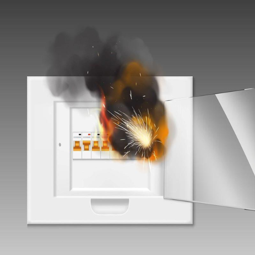
Wires which do not match their required current capacity dimensions produce excessive heat which creates fire dangers and destroys equipment. Proper wire sizing maintains generated heat within safe operating boundaries.
Reducing Voltage Drop
Appliance performance decreases because long wire runs create voltage drop problems which have negative effects on their efficiency. By choosing appropriate wire size the voltage loss during transmission is reduced which enables devices to maintain their expected performance.
Complying with Electrical Codes
The National Electrical Code (NEC) and various local and national electrical codes establish specific wire size requirements that apply to different usage scenarios. The codes establish essential legal requirements which organizations must follow to maintain safe operations.
Enhancing System Efficiency
Proper wire sizing enables efficient power distribution which decreases energy losses. The electric system collection system operates at improved efficiency which results in reduced energy expenditures.
Accommodating Future Expansion
The selection of correct wire dimensions according to upcoming system enhancements allows systems to handle growing requirements without needing costly rewiring work which makes this approach both rational and forward-thinking.
Your understanding of these elements enables you to choose wiring which achieves maximum safety for your electrical projects while maintaining efficient operations.
Overview of NEC Compliance
The National Electrical Code (NEC) serves as a vital standard which protects people through its guidelines about safe electrical system installation and operation in residential and commercial and industrial environments. The National Fire Protection Association (NFPA) updates the NEC every three years to create standards which control electrical wiring and equipment and safety protection solutions. Organizations that follow NEC guidelines achieve both safety improvements and reduced electrical fire and shock and equipment failure hazards.
Key Components of NEC Compliance:
⚡ Safe Wiring Practices
The NEC establishes clear rules for wire sizing, insulation, and grounding to prevent overheating and ensure safety. The proper wire size supports electrical loads while preventing voltage drops according to proper wire sizing. The NEC 2023 update highlights energy efficiency by recommending power usage optimization methods that maintain safety standards.
🛡️ GFCI and AFCI Protection Requirements
Ground-fault circuit interrupters (GFCIs) and arc-fault circuit interrupters (AFCIs) are now mandated in various locations. GFCIs provide protection against electric shocks in areas which contain water, including kitchens and bathrooms and outdoor spaces. AFCIs protect against arc faults, which require installation in all residential areas, including bedrooms and family rooms.
🌱 Energy Efficiency Updates
The recent NEC updates introduced energy-efficient installation requirements, which support the worldwide environmental sustainability movement. The current regulations encompass solar photovoltaic systems and electric vehicle (EV) charging stations and energy storage systems because of technological advancements and the need for green energy solutions.
📊 Data-Driven Industry Trends
The U.S. Fire Administration states that electrical failures serve as the primary cause of residential fires which result in approximately 51,000 fires that occur across the United States every year. The implementation of NEC standards has proven effective in reducing this specific safety risk. NEC standards help establish secure methods for integrating renewable energy systems through their growing use in energy-efficient technologies but they need to create operational standards that will charge up their implementation process.
🔍 Inspection and Enforcement
The local officials of various jurisdictions use qualified personnel to conduct inspections which verify compliance with NEC regulations. The system enables users to discover unsafe methods and code breaches which they can fix without delay. Organizations must keep complete system design records and installation documentation throughout their inspection process to prove NEC compliance.
Professionals can maintain safety standards while implementing modern technologies for energy-efficient project work by following NEC standards and keeping track of new regulatory developments.
Core Answer: Wire Size for 50 Amp Breaker
The National Electrical Code (NEC) establishes wire size requirements for 50-amp breakers which must be followed to guarantee system safety and operational efficiency. The 50-amp circuit requires a wire gauge size of 6 AWG because this wire size can safely carry the current load without overheating. The selection process needs to consider various elements which include wire insulation type, wire run distance, and ambient temperature conditions.
Details and Factors to Consider:
Standard Wire Size for 50 Amps:
The appropriate wire size for 50-amp circuits requires 6 AWG copper wire to be used in most common situations. The use of aluminum wire requires a 4 AWG aluminum upgrade because aluminum wire possesses lower conductivity than copper wire.
Wire Length:
The voltage drop problem arises when the breaker distance to the appliance exceeds 100 feet. The voltage drop needs control through wire size increase to 4 AWG copper or 2 AWG aluminum. The NEC recommends 3% as the maximum voltage drop limit which provides optimal system efficiency.
Temperature Ratings:
The temperature ratings of wire insulation types which include THHN and THWN-2 determine their ampacity. The wires operating in higher ambient temperatures need a bigger gauge to meet compliance requirements. For example, in areas with high temperatures the correct wire size can be selected through insulation rating review and ampacity table examination which exists in the NEC.
Specific Applications:
The wire size and material requirements for RVs electric dryers and specialized equipment need to match the exact specifications of manufacturers and local code requirements.
Conduit Considerations:
The conduit installation process needs both conduit fill capacity assessment and NEC guideline evaluation because these factors determine whether wires have sufficient room to release their heat.
Data Highlights:
- The 6 AWG Copper wire (standard wire for 50 amps) delivers an ampacity value that reaches 65 amps when tested at 75°C.
- The 4 AWG Aluminum wire serves as a replacement option for 50 amps which delivers an ampacity value that reaches 65 amps when tested at 75°C.
- The voltage drop formula for long runs: V_drop = (2 × I × L × R) / 1000 — where I = current in amps, L = one-way wire length in feet, R = resistance in ohms per 1,000 feet.
✅ Direct Answer: Use 6 AWG copper wire or 4 AWG aluminum wire for 50-amp breaker installations.
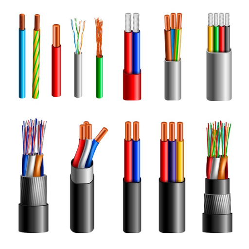
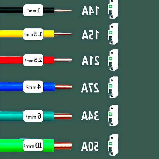
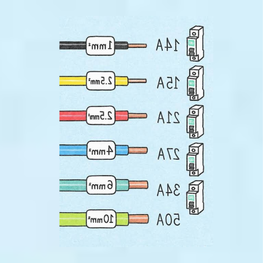
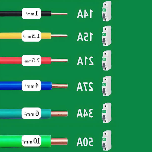
Technical Breakdown of Wire Gauges
The wire gauges determine both the electrical capacity and the safety standards for circuits. This section provides an explanation of wire gauges which includes their ampacity measurement and their typical uses. The data applies the American Wire Gauge (AWG) standard which electrical installations commonly use.
| AWG Size | Max Ampacity | Diameter | Resistance (per 1,000 ft) | Typical Use |
|---|---|---|---|---|
| 12 AWG | 20 amps | 0.0808 in | 1.588 ohms | Household circuits, lighting, outlets |
| 10 AWG | 30 amps | 0.1019 in | 0.9989 ohms | A/C systems, water heaters, major appliances |
| 8 AWG | 40 amps | 0.1285 in | 0.6282 ohms | Electric stoves, permanent kitchen equipment |
| 6 AWG ⭐ | 55 amps | 0.162 in | 0.3951 ohms | 50-amp circuit breaker, hot tubs, EV chargers, large A/C |
| 4 AWG | 70 amps | 0.2043 in | 0.2485 ohms | Feeder connections to subpanels, major machinery |
| 2 AWG | 95 amps | 0.2576 in | 0.1563 ohms | Main power supply, major power distribution |
⚠️ Key Notes on Wire Gauge Selection
- Material Matters: Ampacity varies between copper and aluminum wires. The cost of copper exceeds that of aluminum although copper delivers superior electrical conductivity and reduced electrical resistance. The 6 AWG copper wire operates with a 50-amp breaker yet the 4 AWG aluminum wire becomes necessary because aluminum exhibits higher resistance.
- Voltage Drop: Equipment performance gets affected by excessive voltage drop which requires wire gauge upsizing for longer wire runs.
- Insulation Type: The insulation material (e.g., THHN, THWN) determines a wire’s temperature rating which subsequently affects its ampacity.
The correct wire gauge selection depends on three factors which include electrical load requirements and distance and National Electrical Code (NEC) standards and local building codes. When proper planning and wire sizing procedures are implemented the system achieves better performance because users get protected from safety hazards which include overheating and fire outbreaks.
Understanding AWG: American Wire Gauge
The American Wire Gauge (AWG) system provides standardized measurements for the diameter and cross-sectional area of solid nonferrous electrical conductors with round shapes. The AWG standards from the 1850s established a wiring system which allows electricians and engineers to choose suitable wires for their electrical projects. The wire diameter and thickness decrease as the gauge number increases because the AWG system uses higher numbers to represent thinner wires.
AWG Size Chart and Ampacity
Common AWG sizes appear in the table below together with their cross-sectional areas and diameters and standard ampacity ratings.
| AWG Size | Diameter (inches) | Cross-sectional Area (mm²) | Ampacity @ 60°C | Ampacity @ 75°C | Ampacity @ 90°C |
|---|---|---|---|---|---|
| 14 | 0.0641 | 2.08 | 15 | 20 | 20 |
| 12 | 0.0808 | 3.31 | 20 | 25 | 25 |
| 10 | 0.1019 | 5.26 | 30 | 35 | 40 |
| 8 | 0.1285 | 8.37 | 40 | 50 | 55 |
| 6 ⭐ | 0.1620 | 13.30 | 55 | 65 | 75 |
| 4 | 0.2043 | 21.20 | 70 | 85 | 95 |
| 2 | 0.2576 | 33.60 | 95 | 115 | 130 |
| 1 | 0.2893 | 42.40 | 110 | 130 | 150 |
| 0 (1/0) | 0.3249 | 53.50 | 125 | 150 | 170 |
Key Factors Influencing AWG Selection:
- Electrical Load Requirements: The wire gauge selection process requires users to choose a wire gauge which can handle current needs without generating dangerous heat levels.
- Voltage Drop: The use of thicker cables with smaller AWG numbers decreases voltage drop during long cable runs while preserving system performance.
- Insulation Material: The ampacity ratings depend on insulation material type because wires can handle higher currents when their insulation material has higher temperature ratings.
- Safety Codes and Standards: The National Electrical Code (NEC) and local regulations must be followed to reduce fire and malfunction dangers.
💡 Practical Example
You need to create a 50-amp circuit for an electric vehicle charger. The chart shows that 8 AWG wire meets 75°C insulation ampacity requirements according to the running distance and voltage needs. The cable run needs a wire thicker than 6 AWG because voltage drop will happen during operation through its extended length.
People need to understand AWG because it helps them design electrical systems which will work safely and efficiently throughout homes and businesses and manufacturing facilities. The National Electrical Code (NEC) should be consulted as a reference guide when people need professional advice.
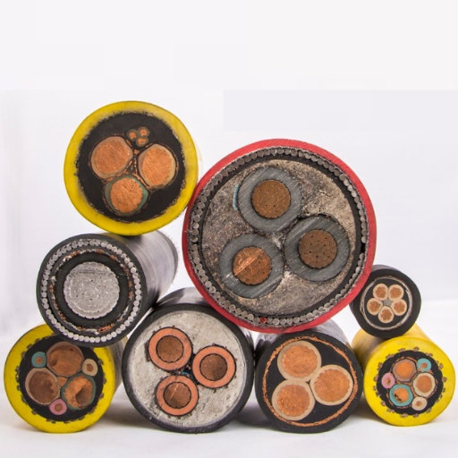
Copper vs. Aluminum Wire: Pros and Cons
The assessment of copper and aluminum wire as electrical system wire material requires an evaluation of the material advantages and disadvantages which each wire type brings. The following five points represent crucial factors which must be evaluated when assessing each wire type.
Wires have specific benefits and drawbacks which require evaluation according to the project requirements. The proper assessment of these factors leads to safe and effective and economical selection processes.
Voltage Drop and Distance: Implications for Wire Size
Voltage drop describes the decrease in voltage that occurs when electricity flows through a conductor. The phenomenon develops into a more crucial matter because electrical resistance causes energy loss during extended wire runs. Engineers need to study voltage drop because it affects their capacity to deliver power while maintaining equipment safety and system efficiency. Here are five important details and factors to consider:
Wire Material
Copper wires have lower resistance compared to aluminum which results in reduced voltage drop over the same distance. However, aluminum wire may still be preferred in certain cases due to cost.
Conductor Size
The use of larger wires which have lower gauge numbers enables better electrical flow because their resistance decreases and thus leads to reduced voltage drop. Conductors need upsizing when they connect to equipment that requires high current or when the power needs to be delivered over extended distances.
Distance of the Run
Longer distances increase the potential for voltage drop. A 100-foot circuit of 120V will experience more voltage drop than a 50-foot circuit because both circuits use identical wire size.
Current Load
Higher current draw results in more resistance and greater voltage drop. When choosing wire size you must consider the total amperage that all connected devices will draw.
Acceptable Voltage Drop Threshold
Standards generally recommend keeping voltage drop within 3% for branch circuits and 5% for the total circuit including feeder and branch components to maintain efficiency and safety.
The proper wire size selection to decrease voltage drop requires you to evaluate these factors according to your voltage performance specifications.
Contextual Factors in Wire Selection
Before selecting wire dimensions for specific wire applications engineers must analyze environmental conditions and operational setup needs. The factors which we study will affect three critical areas performance assessment, long-term durability, and safety regulation compliance. The following environmental conditions need to determine wire selection because current research supports these conditions as essential selection criteria:
| Factor | Details & Impact |
|---|---|
| 🌡️ Ambient Temperature | Wire resistance increases with temperature, and excessive heat can degrade insulation and reduce conductor efficiency. Conductors must apply NEC derating factors when their operating temperature exceeds 30°C (86°F). A 30A conductor can deliver 24A when it operates at a constant temperature of 40°C (104°F). |
| ⛰️ Altitude Considerations | Higher altitudes reduce the ability of conductors to lose heat because the air cooling effect becomes less effective. Research shows that wires operating at altitudes above 2000 feet need to have their ampacity ratings adjusted to maintain safe and effective performance. |
| 💧 Moisture & Corrosive Environments | Wires in coastal and industrial areas which experience high humidity should use insulation materials that have a moisture resistance rating such as THWN for wet locations. The presence of corrosive chemicals in industrial environments requires the use of special coatings or materials which include PVC. |
| ⚙️ Mechanical Impact & Flexibility | Stranded wires provide better flexibility and durability than solid wires for places which experience both vibrations and wire movement and mechanical force exposure. Solid copper conductors experience decreased lifespan because their material undergoes fatigue from continuous wire bending. |
| 📏 Conduit Fill Capacity | Excessive conduit filling creates two problems because it produces excessive heat and decreases system efficiency. The proper conduit sizing process requires compliance with NEC Chapter 9 standards which offer calculations for maximum wire fill based on conduit size and wire insulation specifications. |
| ⚡ Voltage & Load Demand | The latest research highlights the importance of calculating both continuous and non-continuous load demand when determining wire size. For example, a 10-gauge copper wire can carry up to 30A in a standard 120V circuit, but for sustained loads over extended periods, larger wire gauges may be necessary to prevent overheating. |
By taking these contextual factors into account, along with relevant codes and standards, you can ensure optimal wire performance, enhanced system safety, and reduced energy losses in various environments. Always consult the latest NEC guidelines and manufacturer recommendations for precise calculations.
Conduit Requirements for Safe Wiring
Conduits function as essential protective barriers which safeguard electrical wiring from various physical threats and different environmental conditions and all potential dangers which might occur. The safety of electrical systems and their compliance with electrical codes and their operational lifespan depend on selecting and installing conduits through which proper installation and selection processes must be executed.
Types of Conduits:
🔩
Rigid Metal Conduit (RMC)
RMC which uses heavy-duty steel or aluminum materials functions as a superior outdoor conduit solution for use in extreme weather conditions. The system provides advanced physical protection capabilities which enable its use in both industrial and commercial environments.
📦
Electrical Metallic Tubing (EMT)
EMT acts as an indoor conduit solution which people need because it costs less and weighs less than RMC.
🟡
PVC Conduit
PVC creates a durable plastic conduit system which prevents corrosion while functioning in underground and outdoor areas that experience high moisture contact.
🔧
Flexible Metal Conduit (FMC)
This conduit type serves best in locations which require movement to navigate through intricate corners and tight spaces.
💧
Liquid Tight Flexible Conduit (LFMC)
This special FMC version functions as a moisture-resistant conduit solution which operates in environments that experience direct contact with water.
Conduit Fill Capacity
- The NEC regulations require that single wire conduit fill should remain below 40% of the conduit internal cross-sectional space.
- The NEC regulations permit a maximum conduit fill of 31% for two wires and 40% for three or more wires.
- A 1-inch EMT conduit system typically holds a maximum capacity of ten 12-gauge wires.
- The NEC states that conduit systems require their support points to be established at designated intervals that depend on the specific conduit type. All outlets and junction boxes require EMT support every 10 feet and within 3 feet of their locations.
- Over-bending causes wire damage because it creates higher resistance. The NEC establishes different conduit types which require specific minimum bend radius to protect wiring from damage.
- Metal conduits RMC and EMT serve as paths for grounding when they have proper connections which eliminates the need for separate grounding wires.
- The use of PVC and LFMC conduits protects wet locations because those materials create waterproof barriers which prevent corrosion and water ingress. The correct adhesives or watertight fittings need to be used to seal conduit joints.
- Metal conduits provide better performance in high temperatures because PVC conduits face potential deformation and degradation risks over time.
The installation process needs to follow all NEC requirements together with local building regulations to establish safe installation practices. The NEC Article 300 section establishes fundamental wiring regulations which include rules for conduit utilization and protective measures. The NEC 358 standard provides electrical contractors with specification details about EMT while NEC 352 covers PVC specifications and NEC 344 addresses RMC requirements.
Selecting the appropriate conduit enables you to build an electrical system which remains secure and reliable throughout time at any location.
Temperature Ratings and Their Impact on Wire Size
The process of selecting appropriate wire dimensions for electrical systems relies on temperature ratings which serve as a crucial factor. A wire’s insulation must endure operational heat without undergoing any deterioration. When temperature ratings exceed their established limits insulation failure occurs which creates hazardous situations that result in short circuits and fire hazards. The National Electrical Code (NEC) mandates that safe operation requires matching the conductor’s temperature rating with both the operating environment and load requirements.
Temperature Ratings and Their Effects:
| Temperature Rating | Typical Insulation | Application |
|---|---|---|
| 60°C (140°F) | Thermoplastic | General residential and light-duty commercial work |
| 75°C (167°F) | Thermoplastic / Thermoset | Circuits functioning at temperatures exceeding typical conditions |
| 90°C (194°F) ⭐ | THHN, XHHW | Higher temperature capability; typical in industrial environments |
| 105°C (221°F) | Specialty insulation | Equipment wiring and motors |
| 125°C (257°F)+ | Silicone, PTFE | Extreme industrial — ovens, aerospace systems |
You can choose the appropriate wire size and insulation type for different applications by studying temperature ratings and applying NEC guidelines which enhance system performance and safety.
Specific Applications: HVAC, EV Chargers, and Ranges
Electrical wiring serves as a vital system element that delivers power to specific applications while enabling the system to function efficiently and securely. The following section presents complete descriptions together with vital statistics which support these particular uses:
Step-by-Step Installation Safety
The guide contains specific instructions which must be followed to implement safety procedures and current operational methods.
Plan Ahead
Understand the Requirements: The wiring diagram and electrical layout must be reviewed to determine which cable types and breaker sizes and power ratings are necessary. Check Local Codes and Standards: The National Electrical Code (NEC) and other applicable regional codes must be followed because these codes establish safety standards and legal obligations.
Turn Off Power at the Source
The main circuit breaker panel must have power switched off before electrical work begins. The voltage tester should be used to check that electricity is not present in the circuit which will be worked on.
Use Proper Personal Protective Equipment (PPE)
Electricians should wear insulated gloves and safety goggles and flame-resistant clothing when they work with electrical components because these items reduce the danger of shock and burns and other injuries.
Inspect Equipment and Tools
All tools and wiring and equipment must be examined for any evidence of wear and damage and deterioration. All damaged items must be replaced without delay. Broken tools and damaged cables can cause electrical failures which result in accidents.
Install Grounding Systems
Every electrical system needs an appropriate grounding system which protects users from electrical shocks during system faults. The system uses ground wires to direct excessive electrical current into the earth for safe disposal.
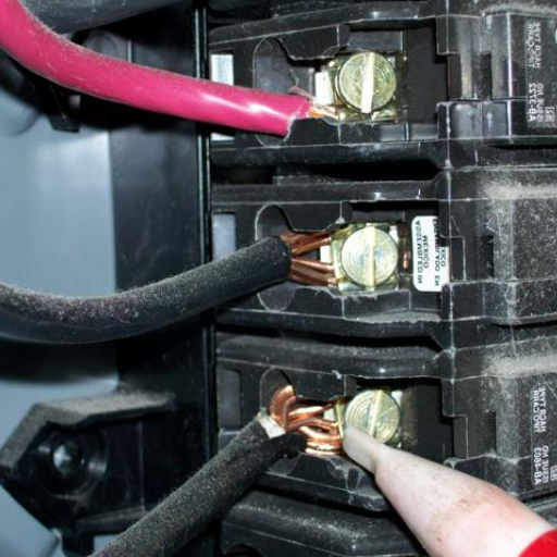
Secure Wiring Connections
The installation needs appropriate wire connectors and terminal blocks which establish safe and dependable electrical links. Loose electrical connections create a dangerous fire risk because they cause wires to overheat and produce arcing. The NFPA reports that residential areas in the United States experienced over 13 percent of electrical fires in 2022 because of poor wiring connections which accounted for these incidents.
Label Circuits Clearly
The complete circuit and breaker labeling process requires the panel box to show all its components in a visible format. The system provides better safety because it decreases confusion during upgrades and troubleshooting processes.
Conduct Inspections
The team will conduct an inspection of all wiring and components after completing the installation to find any mistakes or safety risks. Seek professional assistance if something appears improper. Maintenance work requires the execution of routine inspections. Regular inspections help reduce electrical failures by 40 percent according to industry data.
Test the System
Technicians need to use special testing equipment which includes multimeters for installation testing which they use to check voltage and continuity. The team must verify that all electrical circuits function correctly before they proceed to restore power.
Document the Work
The installation requires the creation of written or digital documents which contain wiring diagrams and breaker sizing information and additional specific details. This document will prove invaluable for troubleshooting or future upgrades.
Best Practices for Connecting to a 50 Amp Breaker
✅ Select the Correct Wire Size
The correct wire size must be selected for your 50-amp breaker requirements. The standard wire size for handling the electrical current safely and effectively without overheating requires 6-gauge copper wire or 4-gauge aluminum wire.
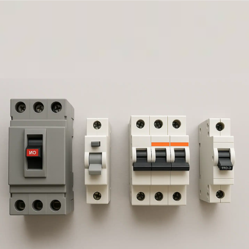
✅ Verify Compatibility of Breaker and Panel
You need to check whether your electrical panel supports the 50-amp breaker installation. The breaker must match both the manufacturer requirements and model specifications of the panel which requires installation.
✅ Turn Off Power Before Starting
You need to turn off the main power supply before starting any work activities. The installation process requires this step because it decreases the possibility of electric shock and injuries occurring.
✅ Connect Wires With Secure Connections
The manufacturer guidelines require you to connect wires to the breaker terminals. Loose connections in the electrical system make it dangerous because they create arcing which results in overheating and fires.
✅ Test the Installation
You must test the circuit after connecting the breaker which will help you check its correct operation. The multimeter which measures voltage needs to be used for checking the system while power restoration requires checking for grounding and wiring faults.
Common Mistakes: Using the Wrong Size Wire
Every electrical installation needs proper wire size selection because of the common installation error which causes dangerous safety situations and equipment failures. The correct wire gauge selection enables safe and efficient management of electrical currents throughout all circuit connections. The National Electrical Code (NEC) requires all wires to be sized according to the ampacity needs of connected devices and the total load of the circuit and the circuit length.
A standard 15-amp circuit needs 14-gauge copper wire as its minimum requirement while a 20-amp circuit requires 12-gauge copper wire for its electrical needs. An undersized wire carries current through its conductor which creates overheating problems that increase fire hazards. Users face unnecessary costs because excessive wire sizing creates safety hazards.
⚠️ Research shows that about 30% of electrical problems in homes originate from inappropriate wire dimensions.
Over time this problem leads to complete circuit shutdowns and tripped breakers and blown fuses. Your home energy efficiency suffers when you select the improper wire size because it creates a voltage drop that impacts all your appliances and devices which rely on the electricity.
The ampacity chart needs to be used as a reference because it helps prevent errors during the process of following local electrical regulations and testing equipment needs to validate your wiring for load requirements. People should hire a licensed electrician to evaluate their wiring system when they feel uncertain about its condition.
Frequently Asked Questions (FAQ)
References
- How to Calculate Breaker Size, Wire Size, and Wattage — This document provides a detailed chart for determining breaker size and the corresponding wire size.
- 50 Amp RV Breaker Box Wiring Diagram — This PDF discusses wire sizes for 50 amp RV breaker boxes, including hot, neutral, and ground connections.
- Branch Circuit Breaker Selection & Wire Sizing — This document includes a wire size chart for various breaker sizes, including 50 amps.