The backup generator of the hospital failed to meet inspection requirements. The generator failed inspection because its wiring system between the transfer switch and electrical panel used undersized wiring which should have been one gauge larger. The inspector used the NEC code violation as evidence to declare the entire project as unsafe. After three weeks of work and spending $8000 on rewiring, the facility obtained compliance for its emergency power system.
This scenario plays out more often than you might think. Wire sizing is not just a technical detail; it is the difference between safe, reliable power and catastrophic failure. The correct wire gauge selection for a 50 amp circuit depends on three factors: standby generator connection, sub-panel installation, and industrial equipment power distribution.
In this guide, we will give you the exact wire sizes for every 50 amp application. You will learn when 6 AWG copper is sufficient, when you need to upsize to 4 AWG or larger, and how factors like distance, temperature, and load type affect your decision. The project needs specific 50 amp circuit wiring which you will learn about by the end of this course.
Quick Answer: What Size Wire for 50 Amp Circuits?
For 50 amp circuits:
- Copper wire: 6 AWG minimum
- Aluminum wire: 4 AWG minimum
The required wire sizes comply with National Electrical Code (NEC) Article 310.16 which establishes rules for conductor ampacities. The values represent primary figures which need adjustment based on multiple conditions. The following situations require you to use larger wire gauges:
The following situations require you to use higher wire sizes:
- Distance over 100 feet: Voltage drop becomes significant
- Continuous loads (over 3 hours): NEC requires 125% sizing
- High ambient temperatures: Derating above 30°C (86°F)
- Multiple conductors in conduit: Bundling reduces heat dissipation
Real-world example: A data center in Phoenix installed 6 AWG copper for their 50 amp generator inlet. The wire extended 150 feet through an uninsulated mechanical room which experienced temperatures above 40°C. The facility faced voltage drop problems which activated their UPS systems within six months. The problem disappeared after they upgraded to 4 AWG. The extra wire expenses totaled $400. The cost of downtime would have created disastrous results.
Need help sizing wire for your standby generator installation? Our engineering team can review your specifications and ensure your installation meets both NEC requirements and your equipment’s needs. Contact us for a technical consultation.
Why Wire Size Matters for 50 Amp Circuits
The process of wire sizing requires precise measurements since it cannot be executed through random selection. The existence of each wire gauge measurement serves to meet particular electrical requirements and physical limitations. The significance of wire size requires understanding because it enables better decision-making than merely consulting a wire size chart.
Safety & Fire Prevention
The United States experiences approximately 51000 electrical fires each year which result in hundreds of fatalities and cause more than one billion dollars in property damage. The primary cause of this problem stems from using undersized wire.
The flow of current through a conductor faces opposition in the form of resistance which develops throughout the entire conductor. The resistance produces heat according to the equation P = I²R which states that power dissipation grows with the square increase of current. A wire that has a 50 amp rating will reach its highest thermal limit when it carries a continuous load of 50 amps. Any undersizing pushes the conductor into dangerous temperature ranges where insulation degrades and ignition becomes possible.
The temperature rating of wire insulation stands equal to the wire gauge as an essential specification. Standard THHN wire has a temperature rating of 90°C which applies to dry environments. The application requires THWN-2 or XHHW-2 which provides equivalent temperature ratings for use in wet locations. The use of incorrect insulation materials in a particular environment leads to a 15-25% decrease in ampacity.
Voltage Drop & Equipment Performance
The performance of electrical equipment suffers because voltage drop operates as an undiscovered threat. The electrical resistance of wire causes voltage to diminish when electricity moves through the wire from one end to another. The NEC standard requires feeders to maintain a 3% voltage drop limit and branch circuits to maintain a 5% voltage drop limit for their total circuits.
The system will encounter voltage drop problems when wires are properly sized yet handle 50 amps of current. A 6 AWG copper conductor shows a 2.08% voltage drop at 240 volts when it carries 50 amps of current for each 100-foot distance. The voltage drop reaches 4.16% at 200-foot distance which brings it near the NEC threshold.
The reason for this importance needs explanation. Motors and compressors use more power because they need to keep their power output constant when voltage levels drop. The increased current flow creates extra heat which shortens equipment durability while it triggers unnecessary circuit breaker trips. The generator operates normally at the panel yet it stops working when it needs to operate at a distance of 150 feet.
Code Compliance & Inspection
The NEC requirements become mandatory for electrical inspectors because the code exists to address specific safety issues which have resulted in actual safety incidents. Multiple liabilities arise from using undersized wire because it leads to:
- Failed inspections: Rewiring costs typically run 3-5x the original material cost
- Insurance denial: Non-compliant installations may void fire coverage
- Legal liability: Injuries from non-compliant electrical work can result in personal liability
- Equipment warranty void: Many manufacturers void warranties for improperly wired installations
Important: Always check local amendments to the NEC. The national code establishes minimum standards which some jurisdictions exceed through their specific commercial and industrial installation requirements.
The Cost of Getting It Wrong
The facilities manager at the Mumbai manufacturing plant selected 6 AWG aluminum wire because he believed it would provide the cheapest solution for the 50 amp power supply to the new CNC machine. The wire ran 120 feet from the sub-panel. The machine experienced intermittent faults during its first three months of operation. The diagnosis identified voltage drop as the problem which resulted in low-voltage alarms. The installation cost for rewiring with 4 AWG copper wire reached three times the initial expense because production downtime needed to be planned. The “savings” on wire became a $12,000 lesson in proper sizing.
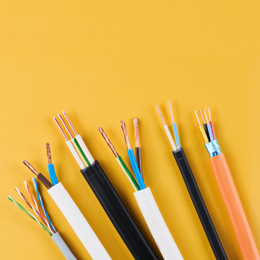
Copper vs. Aluminum Wire for 50 Amp
When choosing between copper and aluminum conductors you need to consider three factors which include their cost and installation difficulty along with their ability to perform over time. The material differences enable you to choose the most suitable material for your specific application.
Ampacity Comparison
Aluminum and copper exhibit distinct differences in their ability to conduct electricity. The volume of aluminum delivers only 61 percent of the electrical conductivity found in copper. The difference requires aluminum wire to use a larger size than copper wire when carrying identical electrical currents.
50 Amp Circuit Requirements:
|
Material |
Minimum Gauge |
NEC Reference |
Weight per 100 ft |
|---|---|---|---|
|
Copper |
6 AWG |
310.16 (75°C) |
39 lbs |
|
Aluminum |
4 AWG |
310.16 (75°C) |
24 lbs |
Both conductors perform identically when properly sized. The key is ensuring you apply the correct gauge for the material selected.
Cost Analysis
Material costs usually determine whether to choose copper or aluminum but need a complete assessment of all expenses related to wire installation.
Material Cost Comparison (approximate, per 100 feet):
- 6 AWG Copper THHN: $180-220
- 4 AWG Aluminum THHN: $85-110
At first glance, aluminum offers a 40-50% material savings. However, total installed cost includes:
- Terminations and lugs: Aluminum requires devices rated for AL/CU or CO/ALR; these cost 15-20% more
- Labor: Aluminum is lighter and easier to pull through conduit, offsetting some material costs
- Anti-oxidant compound: Required for aluminum terminations; minimal cost but necessary labor
- Future maintenance: Aluminum connections require periodic inspection and retorquing
For industrial applications which require extended feeder installations, aluminum provides a cost benefit which makes it the preferred material choice. For shorter runs and critical applications, copper’s reliability and termination compatibility make it the conservative choice.
ShanHua recommendation: We choose copper for generator connections up to 50 feet because it provides reliable performance and simple termination. For longer runs to remote buildings or equipment, aluminum with proper termination hardware offers significant cost savings without performance compromise.
Installation Considerations
Aluminum wire behaves differently than copper during installation and operational processes. The understanding of these differences helps to avoid future problems.
Key differences:
- Expansion and contraction: Aluminum expands 42% more than copper with temperature changes. The thermal cycling process results in connection loosening when termination ends do not receive proper handling.
- Oxidation: Aluminum oxide functions as an insulator while copper oxide maintains its conductive properties. The process of termination preparation requires proper use of anti-oxidant compound.
- Softness: Aluminum exhibits greater softness than copper. Lugs that receive excessive tightening will deform conductors which results in high-resistance connections.
- Compatibility: Aluminum wire cannot be used with all breakers and terminals. The verification of CU/AL or CO/ALR markings must be conducted on every device.
- Installation best practice: Only torque-rated tools should be used for aluminum terminations and all conductor surfaces should be treated with antioxidant compound. The first retorque of connections occurs after 30 days of operation and then annual retorquing occurs for all critical systems.
When to Choose Each
Use this decision framework:
Choose copper when:
- Run length is under 100 feet
- Termination points are limited or difficult to access
- The installation is in a corrosive environment
- You want maximum long-term reliability with minimal maintenance
- The application is critical (hospitals, data centers, life safety)
Choose aluminum when:
- Run length exceeds 100 feet (cost savings multiply)
- You are installing large feeders where weight matters
- Budget constraints are significant
- Proper termination procedures can be consistently followed
- The application is non-critical and accessible for inspection
Get a detailed wire sizing recommendation for your generator installation. Our engineering team can calculate voltage drop, temperature derating, and material costs for your specific run length and environment. Request a technical consultation within 6 hours.
50 Amp Wire Size by Application
The different requirements of various applications create unique wiring needs. The 50 amp RV connection differs from both generator inlets and industrial motor circuits. The distinction between these two systems needs to be understood for correct equipment selection.
Residential Sub-Panels
Sub-panels exist to supply electricity to both outdoor facilities and additional power distribution points. A 50 amp feeder to a sub-panel is common for workshops, garages, and guest houses.
Key considerations:
- Feeder versus branch circuit: Sub-panel feeders have different rules than branch circuits
- Neutral sizing: In some configurations, the neutral can be undersized relative to the hots
- Grounding: Sub-panels in detached buildings require proper grounding electrode systems
- Main breaker: The sub-panel needs a main breaker rated for the feeder ampacity
The recommended wire size for runs under 100 feet is 6 AWG copper or 4 AWG aluminum wire. The recommended wire size between 100-150 feet is 4 AWG copper or 2 AWG aluminum wire.
RV & Camper Connections
Recreational vehicles with 50 amp service need to connect to 240V/120V split-phase power system. The standard 50 amp RV outlet (NEMA 14-50R) is also commonly used for generator inlets in residential installations.
Configuration:
- The system provides 240V between its two hot lines.
- Each leg of the system delivers 120V between its hot line and neutral line.
- The system contains two hot wires and one neutral wire and one ground wire.
- The system uses 6/3 NM-B (Romex) or 6/3 UF-B material for outdoor burial.
The wire system must support complete 50 amp load requirements for each circuit. System components should not be derated based on “diversity factor” estimates until a load calculation is completed according to Article 220.
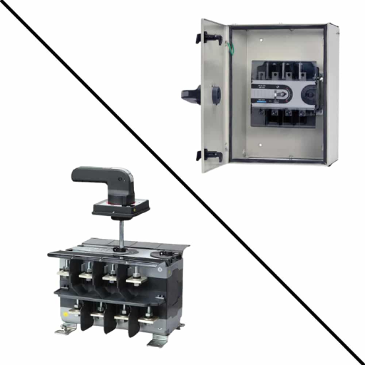
Generator Inlet & Transfer Switches
This is the point at which correct wire sizing which is essential for standby power systems becomes necessary. The standard generator inlet for residential standby generators which produce up to 12000 watts requires a 50 amp connection.
The system design for standby generators follows this configuration pattern:
- Generator → Inlet box → Transfer switch → Main panel
- Transfer switches may exist in two types which are automatic ATS systems and manual systems.
- The wire needs to support both the generator’s complete operational current and its initial power surge.
Wire sizing for generator connections:
|
Run Length |
Copper (AWG) |
Aluminum (AWG) |
Notes |
|---|---|---|---|
|
0-50 ft |
6 |
4 |
Standard installation |
|
50-100 ft |
6 |
4 |
Verify voltage drop < 3% |
|
100-150 ft |
4 |
2 |
Upsize for voltage drop |
|
150-200 ft |
3 |
1 |
Consider voltage drop carefully |
The generator startup surge requires critical evaluation because it generates current which exceeds the rated capacity by 200 to 300 percent during a time period of milliseconds. The breaker must not create false alarms even though the wire does not require surge-based size requirements. Power systems should use breakers which meet generator application requirements and possess appropriate magnetic trip characteristics.
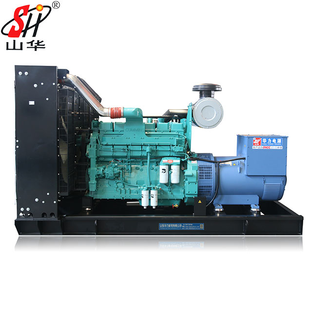
Our generators which generate 10 to 12 kVA of power as silent standby systems use 50 amp inlets for their standard connection method. The installation of these units requires our recommendation to use 6 AWG copper for distances up to 75 feet and 4 AWG copper for distances beyond that point to the transfer switch. The system requires this setup to maintain full voltage at the ATS during generator startup when voltage regulation reaches its peak importance.
Welding Equipment
Arc welders create distinct issues which require special wire sizing methods. The NEC Article 630 contains rules which specifically govern welder branch circuits whereas standard circuits for motors and resistive loads use different regulations.
The main factors which determine welding operations include:
- Duty cycle impacts conductor sizing because welders operate as non-continuous loads.
- The wire needs to match the welder’s primary current rating
- The manufacturer requires you to use the minimum circuit ampacity (MCA) specification from the nameplate rating.
Typical 50 amp welder requirements:
- Dedicated circuits need 6 AWG copper wire for distances under 100 feet
- The nameplate contains information about the welder’s power factor and duty cycle
- Welding performance decreases substantially when operating with low voltage; therefore you must evaluate voltage drop as an important factor.
Industrial Equipment & Motors
Three-phase motors and industrial equipment often require 50 amp circuits. The National Electrical Code Article 430 establishes special requirements for motor circuit sizing.
Motor circuit sizing:
- Branch circuit conductors must carry 125 percent of the motor’s full-load current (FLC) during operation.
- The breaker size should not exceed 250 percent of the FLC value when using inverse-time breakers.
- The wire size should be selected according to the ampacity tables which apply to 75°C termination ratings.
Example: A 10 HP motor which operates at 230V in three-phase mode has a full load current of 28 amps. The branch circuit conductor must be sized for 28 × 1.25 = 35 amps minimum. A 6 AWG copper conductor (rated 65A at 75°C) provides adequate capacity with margin for voltage drop on longer runs.
Important: Always use the motor nameplate FLC for calculations, not the breaker size or theoretical load. Motors draw 5-7x FLC during starting, but this inrush is brief and does not require wire upsizing.
EV Charging Stations (Level 2)
Level 2 electric vehicle chargers need 50 amp circuits because they deliver 40 amp charging which follows the 80% rule that governs continuous loads.
Configuration:
- The system requires a 50 amp breaker together with 6 AWG copper or 4 AWG aluminum wiring and either NEMA 14-50 outlet or hardwired system.
- The system needs a dedicated circuit which cannot support any additional electrical equipment.
According to the 80% rule continuous loads which maintain their peak current for over 3 hours must use equipment sized at 125% of their actual load. The 40 amp EV charger needs a 50 amp circuit because 40 times 1.25 equals 50.
Voltage Drop: When to Upsize Your Wire
The primary reason for using larger wires occurs because voltage drop problems require it. The ability to understand proper situations for wire upsizing enables users to prevent both performance issues and equipment failures.
The 3% Voltage Drop Rule
The NEC guidelines state that voltage drop for feeders should not exceed 3% while branch circuits should have an overall voltage drop limit of 5%. These limits ensure:
- Motors maintain operation at their named voltage settings
- Heating elements produce their specified heating output
- Electronic equipment operates with consistent electrical power
- Breakers do not nuisance trip from low-voltage high-current conditions
The 3% voltage drop for a 240V circuit corresponds to 7.2 volts. The circuit must provide at least 232.8 volts to the load during maximum current operation.
Wire Size Chart by Distance (50 Amp, 240V)
Select wire size according to run length by using these charts. The calculations use copper conductivity at 75°C and aluminum conductivity at 75°C to calculate for single-phase 240V system.
Copper Wire (THHN/THWN-2, 75°C):
|
Distance |
6 AWG (4.37 V drop) |
4 AWG (2.74 V drop) |
3 AWG (2.17 V drop) |
2 AWG (1.72 V drop) |
|---|---|---|---|---|
|
50 ft |
2.18% |
1.37% |
1.09% |
0.86% |
|
100 ft |
4.37% |
2.74% |
2.17% |
1.72% |
|
150 ft |
6.55% |
4.11% |
3.26% |
2.58% |
|
200 ft |
8.74% |
5.48% |
4.34% |
3.44% |
Aluminum Wire (THHN/THWN-2, 75°C):
|
Distance |
4 AWG (2.74 V drop) |
2 AWG (1.72 V drop) |
1 AWG (1.37 V drop) |
1/0 AWG (1.08 V drop) |
|---|---|---|---|---|
|
50 ft |
2.74% |
1.72% |
1.37% |
1.08% |
|
100 ft |
5.48% |
3.44% |
2.74% |
2.16% |
|
150 ft |
8.22% |
5.16% |
4.11% |
3.24% |
|
200 ft |
10.96% |
6.88% |
5.48% |
4.32% |
How to use this chart: First you need to determine your run length and your required voltage drop percentage. The percentage exceeds 3% which requires you to select the next larger wire size until you achieve an acceptable voltage drop.
Example: You need to run 50 amps at 240V for 150 feet. According to the copper chart:
- 6 AWG: 6.55% drop (unacceptable)
- 4 AWG: 4.11% drop (marginal)
- 3 AWG: 3.26% drop (marginal)
- 2 AWG: 2.58% drop (acceptable)
The correct wire size for this installation involves 2 AWG copper because 6 AWG satisfies the basic ampacity rules.
Calculating Voltage Drop (Formula)
The voltage drop formula provides exact calculations through this equation:
VD = (2 × K × D × I) / CM
- The formula defines voltage drop through VD while using K to represent conductor resistance which has values of 12.9 for copper and 21.2 for aluminum at 75°C.
- The formula defines distance through D which measures one-way distance in feet.
- The formula defines current through I which measures current in amps.
- The formula defines conductor circular mils through CM which has values of 26,240 for 6 AWG and 41,740 for 4 AWG and 52,640 for 3 AWG and 66,360 for 2 AWG.
Example calculation: 50 amps, 120 feet, 6 AWG copper
VD = (2 × 12.9 × 120 × 50) / 26,240
VD = 154,800 / 26,240
The result shows a voltage drop of 5.9 volts which represents a 2.46% drop at 240V.
The calculation proves 6 AWG wire meets requirements for this installation although it approaches the 3% boundary. Pro tip: For critical applications like data centers or medical equipment, design for 2% voltage drop rather than 3%. The additional cost of larger wire is minimal compared to the cost of equipment malfunction or downtime.
Temperature Derating & Environmental Factors
The wire ampacity tables work under standard conditions as their basic operating assumption. The actual installations which take place in the field need to decrease equipment capacity because they will encounter elevated temperatures and multiple wire systems and wet environmental conditions.
Ambient Temperature Adjustments
Standard ampacity tables assume 30°C (86°F) ambient temperature. The wire needs derating because it operates in hot environments which decrease its heat dissipation capacity.
Temperature derating factors (from NEC 310.16):
|
Ambient Temp (°C) |
Derating Factor (60°C wire) |
Derating Factor (75°C wire) |
Derating Factor (90°C wire) |
|---|---|---|---|
|
31-35 |
0.91 |
0.94 |
0.96 |
|
36-40 |
0.82 |
0.88 |
0.91 |
|
41-45 |
0.71 |
0.82 |
0.87 |
|
46-50 |
0.58 |
0.75 |
0.82 |
|
51-55 |
0.41 |
0.67 |
0.76 |
Example derating calculation:
You are installing 6 AWG THHN copper (90°C rated, 75A ampacity) in a mechanical room where ambient temperature reaches 45°C.
The adjusted ampacity of the system calculates to 75 amps multiplied by 0.87 which equals 65.25 amps.
The 6 AWG wire remains suitable for use because 65.25 amps exceeds your 50 amp requirement. At 50 degrees Celsius ambient temperature the derating factor decreases to 0.82.
The adjusted ampacity calculates to 75 amps multiplied by 0.82 which equals 61.5 amps.
The situation remains acceptable but there exists reduced capacity. The adjusted ampacity at 55 degrees Celsius calculates to 75 amps multiplied by 0.76 which equals 57 amps.
The system now has 7 amps available as headroom. The system requires an upgrade to 4 AWG for continuous loads and future upgradeable installations at temperatures above 50°C.
Conduit Fill & Bundling Effects
The shared heat from multiple conductors in a conduit or cable tray system decreases the ampacity of each conductor. The National Electrical Code specifies that NEC Article 310.16(C) requires derating when more than three current-carrying conductors exist within a raceway system.
Adjustment factors for conduit fill:
|
Number of Current-Carrying Conductors |
Derating Factor |
|---|---|
|
4-6 |
80% |
|
7-9 |
70% |
|
10-20 |
50% |
|
21-30 |
45% |
Your system operates with four 50 amp circuits which use eight current-carrying conductors that operate through a single conduit. Your 6 AWG copper (65A at 75°C) must be derated:
Adjusted ampacity = 65 × 0.70 = 45.5 amps
The 45.5 amps value does not meet the requirements for a 50 amp circuit. You must upsize to 4 AWG copper (85A at 75°C):
Adjusted ampacity = 85 × 0.70 = 59.5 amps
The circuit now has the correct capacity for its electrical load.
Note: Grounding conductors and neutrals in balanced three-phase circuits do not count as current-carrying conductors for derating purposes. However, in single-phase circuits, the neutral carries current and must be counted.
Wet/Dry Location Ratings
The different wire insulation types have established moisture protection standards which define their maximum moisture tolerance.
- THHN wire insulation is designed for use in dry areas with a maximum temperature of 90°C.
- THWN-2 wire insulation can be used in both wet and dry environments with a maximum temperature of 90°C in both conditions.
- XHHW-2 wire insulation can be used in both wet and dry environments with a maximum temperature of 90°C in both conditions.
- USE-2 wire insulation is designed for underground applications with direct burial capabilities at a maximum temperature of 90°C.
- UF-B wire insulation is designed for underground feeder applications which allow direct burial at a maximum temperature of 60°C.
The critical difference between THHN and THWN exists because these two wires receive dual certification as THHN/THWN-2. The wire markings need to be checked by you. The installation process requires wet-rated wiring for any area that has the potential to become damp. The use of dry-location wires in wet environments results in both code violations and dangerous safety situations.
The installation of generator inlet boxes and outdoor transfer switches needs wet-location wire because that area requires special electrical standards. The main indoor run will connect to outdoor areas at the end points. All generator connection wiring needs to use either THWN-2 or XHHW-2 as the required specifications.
Wire Types & Insulation for 50 Amp

The letters printed on wire insulation serve a purpose which provides essential information about three specific temperatures, moisture protection capacity, and suitable uses.
THHN/THWN-2 (Indoor/Conduit)
THHN stands for Thermoplastic High Heat-resistant Nylon-coated. The wire type which people use most frequently in commercial and industrial settings operates as their standard choice.
Specifications:
- The temperature rating reaches 90°C for both dry and wet conditions when the system operates at dual-rated THWN-2.
- Voltage: 600V
- The system operates through three connection methods which include conduit and cable tray and machine tool wiring.
- The system has a moderate pricing structure.
- The system serves best for wiring purposes in indoor environments which require conduit installation together with dry industrial operations.
The nylon coating establishes superior protection against abrasion damage which occurs during pulling operations. The system does not allow for direct burial according to THHN/THWN-2 standards. Use USE-2 or UF-B for underground applications.
XHHW-2 (Wet Locations)
The term XHHW represents the material which contains XLPE (cross-linked polyethylene) that provides High Heat resistance and Water resistance. The material provides better protection against moisture and chemical substances when compared to THHN.
Specifications:
- The system operates at two temperature conditions which include 90°C dry and 90°C wet.
- The system operates at a voltage level of 600V.
- The system operates in three different environments which include outdoor conduit and wet locations and chemical plants.
- The system operates at a cost which exceeds THHN by 15-20%.
The system operates best under three specific conditions which include outdoor installations and generator connections and industrial plants which experience moisture exposure and chemical vapor presence.
The cross-linked polyethylene insulation in XHHW-2 provides superior durability compared to PVC-based THHN during extreme environmental conditions. The extra expense for generator installations becomes necessary because the equipment needs to function reliably over an extended period.
USE-2 (Underground/Direct Burial)
The term USE describes Underground Service Entrance. The USE-2 system permits direct burial installations which do not require the use of conduit.
Specifications:
- The temperature rating reaches 90 degrees Celsius.
- The system operates at a voltage of 600 volts. The system supports two types of installation direct burial and underground feeder installation.
- The product price matches XHHW-2.
- The product works best for underground generator feeds which connect to outdoor sub-panels and trench runs which extend to outbuildings.
Installation requirements:
The minimum requirement for burial depth establishes 24 inches which local codes may adjust.
The system requires PVC conduit or cable protection for grade protection at locations where it exits from the ground.
The system requires trench slopes which direct water away from buildings.
The company recommends USE-2 for generator installations which operate from remote locations to protect their most vital areas.
The system allows future replacement without additional trench work. The system provides protection against digging activities.
SER Cable (Service Entrance)
The Service Entrance Round defines its abbreviation as SER. The cable assembly operates as a multi-conductor conduit which supplies electrical power to both service entrance locations and feeder distribution systems.
The following configurations exist:
- The 6/3 SER system consists of two 6 AWG hot wires and one 6 AWG neutral wire and one 8 AWG ground wire.
- The 4/3 SER system consists of two 4 AWG hot wires and one 4 AWG neutral wire and one 6 AWG ground wire.
The system works best for residential sub-panels which need feeder runs that do not require conduit installation and for multi-wire circuit systems which need quick setup.
Limitations:
- SEU and USE-2 are the only burial options for this product because direct burial is not permitted.
- The product operates only within dry environment spaces
- The cable’s wider dimension makes it more difficult to bend than regular conductor segments.
SER cable according to code requirements includes a reduced neutral which designers sized based on load requirements. The neutral size must be checked for sufficiency through Article 220 load calculations to support 120V loads which exceed 50 amp sub-panels.
Installation Best Practices
Proper installation technique ensures your wire sizing calculations translate into safe, reliable circuits.
Breaker Compatibility
The electrical system of your building uses circuit breakers as its main method for protecting wiring against overcurrent situations. The system needs to have proper breaker and wire system operation through their correct size matching.
Breaker sizing rules:
- The breaker must protect the wire ampacity
- Standard breakers: Size to wire ampacity at 75°C termination rating
- The 125% sizing rule for continuous loads requires a 50 amp continuous load to use a 62.5 amp breaker which must be rounded up to the next standard size.
Example: 6 AWG copper has 65A ampacity at 75°C. The maximum standard breaker size is 70 amps for non-continuous loads, 60 amps for continuous loads (60 × 1.25 = 50).
AFCI/GFCI considerations: If your installation requires Arc-Fault or Ground-Fault circuit interrupters, verify the breaker is compatible with your wire type and that the combination has been tested by the manufacturer. The aluminum wire connection fails to function correctly with some AFCI breakers.
Terminal & Lug Ratings
The most frequent failure point in electrical installations occurs at termination points. Future problems occur when terminals get selected and installed through incorrect methods.
Terminal ratings:
- CU only: This terminal type permits only copper wire.
- AL/CU: This terminal type permits both aluminum and copper wire.
- CO/ALR: This terminal type specifically supports aluminum which has an older designation that remains valid today.
Installation torque:
- A torque screwdriver needs to get used for all termination work.
- The process of over-tightening leads to damage of both conductors and terminals.
- The process of under-tightening results in connections that have high resistance issues. After 30 days of thermal cycling aluminum connections need to undergo retorqueing.
- The anti-oxidant compound needs to get applied for all aluminum terminations.
The compound:
- The compound stops oxidation from happening on aluminum parts which remain unprotected.
- The compound enhances the electrical flow throughout the connection.
- The compound maintains its performance throughout different temperature conditions.
Before putting aluminum components into terminals you need to apply compound on their visible aluminum areas.
Grounding Requirements
Safety during fault conditions requires proper grounding methods. 50 amp circuits require equipment grounding conductors sized per NEC Table 250.122.
People need to know about equipment grounding conductor sizes which apply to 50 amp circuits as follows:
- 10 AWG copper (minimum code requirement)
- 8 AWG copper (common practice, provides margin)
- 8 AWG aluminum (if used with aluminum phase conductors) The grounding conductor carries fault current only during abnormal conditions. The conductor does not carry regular operating current because it has different ampacity requirements than phase conductors. The breaker will trip during fault conditions if you size the system components correctly.
When to Consult an Electrician
The guide offers enough information for people to make informed decisions but certain situations need professional electrical contractors.
- Service entrance modifications require the connection to utility service equipment.
- Panel upgrades need to replace main distribution panels.
- Load calculations apply to installations that require multiple power assessments.
- Local code variations exist in jurisdictions which have made changes to the NEC.
- The inspection requirements become active when permits and inspections need to be conducted.
Electrical work leads to high liability risks for professional electricians. The installation needs professional installation with proper insurance to protect against future claims because it serves multiple users which include tenants and employees and customers.
Need a standby generator installed with proper wire sizing and transfer switch coordination? ShanHua’s technical team can recommend qualified electrical contractors in your region, or provide detailed installation specifications for your contractor to follow. Request installation support.
Frequently Asked Questions
Can I use 8 gauge wire for 50 amps?
The electrical capacity of No. 8 AWG copper wire reaches 40 amps when the temperature reaches 75 degrees Celsius. The use of 8 AWG wire for a 50 amp circuit violates NEC Article 310.16 which results in an increased fire danger. The wire will overheat under continuous 50 amp load, which will damage insulation and create a fire risk through material ignition.
Can 6 AWG handle 60 amps?
The 6 AWG copper wire has a 75°C rating which allows it to handle 65 amps so its actual capacity reaches 60 amps. The NEC requires 125% sizing for 60 amp continuous loads because the load lasts more than three hours: 60 × 1.25 = 75 amps required conductor ampacity. For continuous 60 amp loads, you need 4 AWG copper (85A at 75°C).
What’s the difference between 220V and 240V wire sizing?
The wire sizing requirements for 220V circuits and 240V circuits remain the same. Single-phase residential service and light commercial service use both voltages as standard nominal voltages. Wire sizing depends on current (amps), not voltage. The same wire size is needed for a 50 amp circuit which operates at 120V and 240V and 480V.
Do I need a neutral for a 50 amp generator connection?
Your generator system needs transfer switch configuration assessment because it depends on your particular generator setup.
- Your 120/240V generator requires a neutral connection to operate its 120V circuits because it needs that connection.
- The system needs no neutral connection for 240V-only loads because it handles pure 240V welders without needing one.
- Most residential transfer switches need neutral power to pass through because their design needs that requirement to function properly.
The generator output configuration together with the transfer switch requirements needs verification. Most residential standby generators produce 120/240V split-phase power which requires a neutral conductor to operate.
How deep to bury 50 amp wire?
burial depth depends on wire type and protection:
- UF-B cable (direct burial): 24 inches minimum
- USE-2 cable (direct burial): 24 inches minimum
- THHN/THWN-2 in conduit requires 18 inches of depth through rigid metal or intermediate metal conduit and 24 inches through PVC conduit.
The National Electrical Code needs to be checked for local amendments because specific locations mandate deeper requirements. Mark underground routes with warning tape 12 inches above buried cables to prevent damage from future excavation.
Can I run 50 amps on 12 gauge wire?
The answer to your question is no. The maximum current capacity of 12 AWG copper wire stands at 20 amps. The application of 50 amps through 12 AWG wire will result in immediate dangerous overheating. The wire insulation will melt, creating a short circuit and fire hazard. The installation of this code violation represents one of the most hazardous electrical fire hazards.
What size wire for 50 amp at 100 feet?
The measurement of voltage drop starts at a distance of 100 feet.
- Copper: 6 AWG is acceptable (4.37% drop at 240V, slightly over the 3% recommendation but within NEC guidelines). Sensitive equipment needs 4 AWG as its power requirement solution.
- Aluminum: 4 AWG experiences 5.48% drop at 240V. The voltage drop requirements necessitate that you use 2 AWG aluminum as your replacement material. The voltage drop calculation requires you to upsize your equipment whenever the drop reaches 3% or higher.
Is aluminum wire safe for 50 amp circuits?
The installation of aluminum wire requires correct installation methods to ensure safe use which exists since decades in residential commercial and industrial locations. The key requirements are:
- Use only wire rated for your application (THHN/THWN-2 XHHW-2 USE-2)
- Terminate only on devices rated for aluminum (CU/AL or CO/ALR)
- Apply anti-oxidant compound to all terminations
- Torque to manufacturer specifications
- Inspect and retorque connections periodically
Aluminum wiring functions safely in millions of residential and commercial structures. The horror stories from the 1960s involved specific connection types that are no longer used. Modern aluminum wire becomes safe and reliable through proper termination methods.
Conclusion
The process of selecting appropriate wiring for a 50 amp circuit becomes easy after acquiring knowledge about the necessary factors. The baseline answer is simple: 6 AWG copper or 4 AWG aluminum. Yet actual electrical work goes beyond this uncomplicated scenario which exists for electrical engineers.
The final specification results from four factors: distance, temperature, load type, and application. A 50 foot run to a garage sub-panel is entirely different from a 150 foot underground run to a standby generator. The understanding of voltage drop and temperature derating with continuous load factors enables you to ensure reliable performance of your installation throughout its entire operational lifespan.
The cost difference between properly sized wire and undersized wire is minimal compared to the cost of rewiring equipment damage or downtime. When in doubt, upsize. The use of larger wire results in:
- Reduced voltage drop which improves equipment functionality
- Additional capacity for future electrical system expansion
- Wires operate at reduced temperatures which results in extended protection against electrical faults
- The system meets safety margins established by code requirements.
Key takeaways:
- The minimum wire size for 50 amp circuits requires 6 AWG copper or 4 AWG aluminum.
- The wire size should increase when the distance exceeds 100 feet to maintain proper voltage levels.
- The 125% sizing factor should be used to calculate the required size of equipment for handling continuous electrical loads.
- The installation of outdoor and generator systems requires the use of wires which have wet-location rating.
- You need to check whether the termination points work with aluminum conductors.
The generator system installation requires correct wire sizing as one essential element which needs to be done. ShanHua’s engineering team can help you specify the right generator size, transfer switch, and wiring for your critical loads. Our company provides reliable power solutions which maintain operational continuity for hospitals data centers and industrial facilities through our 25 years of power generation experience and our ISO9001 CE and CCC certified products.
Request a generator specification and wire sizing consultation — our technical team responds to all inquiries within 6 hours, 24/7, 365 days a year.