The safety measures and operational efficiency of electrical systems depend on proper wire sizing which constitutes their fundamental requirement. The proper operation of your electrical system depends on your ability to select suitable wire size for your 30-amp circuit because this task requires more than just technical expertise. This blog post will guide you through the essentials of selecting the appropriate wire size for a 30 amp breaker, explaining why this choice matters and how it impacts the performance and safety of your setup. The article provides essential insights which help homeowners who want to handle DIY projects and professional electricians who need to refresh their knowledge make better choices. The technical information needs to be simplified into specific tasks which will enable you to stop expensive errors that could put you in danger.
Understanding Wire Size and Gauge
The wire size which matches a 30 amp breaker requirement is 10-gauge copper wire. The 30 amp breaker needs a wire which can manage its current without experiencing overheating problems because 10-gauge wire delivers enough power capacity and protection needs. Equipment problems together with fire hazards emerge when people use wires which do not meet required size specifications. You must confirm that your wiring system complies with all applicable local regulations because you should contact a certified electrician for guidance when you have any uncertainties.
What is Wire Gauge?
The wire gauge system establishes standard measurements for electrical wire diameters, where lower gauge numbers correspond to thicker wires that can handle greater electrical loads.
Importance of Ampacity in Wire Selection
Ampacity defines the maximum electrical current that a wire can safely carry without exceeding its temperature limit for safe operation. The selection of the proper wire with its correct ampacity value becomes essential to protect electrical systems because it enables both safe operation and efficient performance and extended system lifespan. The importance of ampacity for wire selection exists through five major factors which follow this introduction.
Preventing Overheating
The use of a wire with insufficient ampacity leads to wire overheating which results in both insulation damage and performance reduction and fire hazard development.
Compliance with Electrical Codes
Building and electrical codes require specific ampacity ratings to protect safety while ensuring that installations follow established industry standards.
Handling Increased Electrical Demand
Wires with proper ampacity specifications can protect against electrical overloads while they carry the complete power requirements of modern electrical systems during peak usage times.
Prolonged Equipment Life
Correct ampacity selection protects wiring systems while it enables devices to work at maximum efficiency for extended periods.
Reduced Energy Loss
The system achieves better energy efficiency because proper ampacity decreases wiring resistance which leads to less energy loss throughout the entire system.
How to Read a Wire Size Ampacity Chart
The wire size ampacity chart shows the highest electrical current limit that a conductor can handle without experiencing overheating problems. The chart requires proper understanding because it protects electrical systems from failures while maintaining their optimal performance. The text below shows the main components needed to interpret the chart, together with specific information and numerical data:
Wire Gauge (AWG)
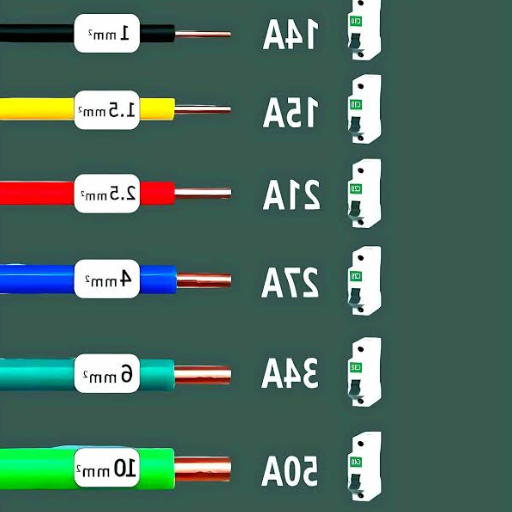
The American Wire Gauge (AWG) system provides a standardized method for measuring electrical wire thickness. The wire thickness increases with higher electrical current capacity when the gauge number decreases. For example:
- ▶ 12 AWG can handle up to 20 amps, making it suitable for household circuits.
- ▶ 10 AWG can handle up to 30 amps, which people commonly use to power air conditioners and electric water heaters.
Conductor Material
Different materials, such as copper or aluminum, vary in their ability to conduct electricity. Copper wires are more commonly used because they offer higher electrical conductivity and better durability than aluminum wires which need special adjustments for their ampacity handling. For instance:
- ▶ A 10 AWG copper wire carries 30 amps.
- ▶ The capacity of a 10 AWG aluminum wire is limited to 25 amps.
Temperature Rating of Insulation
The wire insulation temperature rating determines the maximum current capacity of the wire. Ampacity measurements use standard temperature points which include 60°C (140°F), 75°C (167°F), and 90°C (194°F). The wire insulation needs to match the system’s temperature requirements to prevent overheating.
Ambient Temperature Adjustment
The wire’s electrical capacity changes with the temperature conditions of its environment. The chart shows specific correction factors which need to be applied when temperatures exceed 30°C (86°F). For example:
- The wire’s ampacity at 40°C (104°F) requires complete recalculation because it shows a major decrease in capacity.
Bundling Adjustments
The heat dissipation from multiple wires operating together in a conduit creates greater difficulties which result in reduced safe operating capacity. The grouped cables need bundling corrections to maintain their safe operational standards.
Example Data for Common Residential Applications
| Wire Size (AWG) | Material | Max Ampacity | Typical Application |
|---|---|---|---|
| 14 AWG | Copper | 15 amps | Lighting circuits |
| 12 AWG | Copper | 20 amps | General outlets |
| 10 AWG | Copper | 30 amps ✓ | Heavy-duty appliances |
| 8 AWG | Copper | 40 amps | Subpanels, electric ranges |
The wire size ampacity chart requires you to consider wire gauge, conductive materials, insulation temperature, ambient temperature, and bundling adjustments for safe and efficient electrical installation. The NEC (National Electrical Code) and other applicable codes require you to check for compliance and follow their guidance.
Determining the Right Wire Size for a 30 Amp Circuit
The selection of appropriate wire dimensions plays a vital role in maintaining operational efficiency while protecting against hazards which arise during circuit design upgrades to accommodate 30 ampere electrical loads. The electrical code standards require the use of 10 AWG copper wire to create 30-amp circuits. The standard recommendation about wire size needs to be adjusted because different factors influence wire performance which includes wire material, insulation type, operating temperature, and circuit distance.
Wire Material
The ampacity of a wire depends on whether it is made of copper or aluminum. The 10 AWG copper wire can handle 30 amps for most residential applications because copper provides better conductivity. The use of aluminum wire requires an 8 AWG gauge because of its lower conductivity when compared to copper which needs a thicker wire gauge for equivalent load capacity.
Voltage Drop and Circuit Length
The voltage drop problem emerges for circuits that extend beyond 100 feet of distance. A typical recommendation is to aim for a voltage drop of less than 3%. The wire size needs to be increased because excessive voltage loss must be prevented. A circuit length of 100 feet or more requires an 8 AWG copper wire for 30-amp loads to maintain proper system performance.
Insulation and Temperature Ratings
Wire insulation comes with temperature ratings which determine its maximum ampacity limit. The following example demonstrates this concept:
- ▶ The 60°C insulation of standard residential wiring allows 10 AWG copper wire to carry 30 amps.
- ▶ The 90°C insulation of high-heat applications enables wires to conduct higher current levels which depend on their surrounding environment.
⚠️ The insulation rating must be checked for all circuits that operate in high-temperature conditions or use bundled cables because these situations require changes to the ampacity limits.
Ambient Temperature Adjustments
You must reduce the wire’s ampacity when it operates in extremely hot environments such as summer attic spaces. The National Electrical Code (NEC) provides adjustment factors for ambient temperatures above 86°F (30°C).
Conduit and Bundling
The heat dissipation from bundled wires decreases when they are installed in a conduit or raceway. The NEC Article 310.15(B)(3)(a) requires ampacity adjustments to be made for equipment to avoid overheating.
Wire Ampacity Data Table (30-Amp Circuit Examples)
| Wire Material | Wire Gauge (AWG) | Insulation Rating | Maximum Ampacity |
|---|---|---|---|
| Copper | 10 AWG | 60°C | 30 amps |
| Copper | 10 AWG | 75°C | 35 amps |
| Copper | 10 AWG | 90°C | 40 amps |
| Aluminum | 8 AWG | 60°C | 30 amps |
| Aluminum | 8 AWG | 75°C | 35 amps |
| Aluminum | 8 AWG | 90°C | 40 amps |
✅
Recommendations and Compliance: The National Electrical Code (NEC) together with local regulations must be followed for proper compliance with the established detailed guidelines. The licensed electrician should be contacted by people who experience uncertainty because this expert will determine if the wiring complies with both safety standards and code requirements.
The Distance and Voltage Drop Determination Process
The process of calculating voltage drop becomes essential for electrical system design because it ensures both system safety and functional effectiveness. When electrical current travels through a conductor the voltage drop occurs because the conductor has natural resistance. The operation of electrical devices becomes inefficient and equipment suffers damage when voltage drop exceeds established acceptable limits.
Key Formula for Voltage Drop
Single-Phase Systems
Voltage Drop (V) =
(2 × Length × Current × Resistance) ÷ 1,000
Three-Phase Systems
Voltage Drop (V) =
(√3 × Length × Current × Resistance) ÷ 1,000
Where:
- Length — the one-way distance of the conductor (in feet or meters).
- Current — the load current in amperes (A).
- Resistance — the resistivity of the conductor material, often given in ohms per 1,000 feet or meters.
Voltage Drop Limits
According to the NEC, the recommended voltage drop should not exceed:
- ▶ 3% for branch circuits or feeders.
- ▶ 5% for combined feeder and branch circuits.
Example Calculation
Let’s calculate the voltage drop for a 100-foot run of copper wire with a load current of 30 amps at 120 volts. Assume the wire is 8 AWG with a resistance of 0.628 ohms per 1,000 feet (for copper at 75°C).
- Calculate the total wire length (round trip):
100 feet × 2 = 200 feet - Insert the values into the formula:
Voltage Drop (V) = (2 × 100 × 30 × 0.628) ÷ 1,000 = 3.768 volts - Calculate the percentage of voltage drop:
Voltage Drop % = (3.768 ÷ 120) × 100 = 3.14%
✅ This falls just within the NEC’s recommendation for voltage drop in branch circuits.
Materials and Conductors: Electrical systems use both copper and aluminum as common conductors, but their performance characteristics show different outcomes. Copper exhibits lower resistivity than aluminum, which enables Copper to decrease voltage drop during long-distance power transmission. The application and budget requirements will determine which material is better between aluminum and copper because aluminum offers lower weight and cost advantages.
Distance Considerations: For longer distances, use larger wire sizes to reduce resistance. The voltage drop and load current must be considered together when selecting wire size.
Voltage Drop Calculators: Users benefit from online voltage drop calculators that deliver improved accuracy and operational efficiency. The calculation process becomes easier through tools that electrical standards organizations and reliable manufacturers provide because these tools calculate conductor type, size, and load conditions automatically. The electrical system will remain efficient and compliant with safety standards through your ability to calculate voltage drop accurately.
Choosing Between Copper and Aluminum Wire
The selection of wires for electrical systems between copper and aluminum requires people to assess multiple factors which include the electrical conductivity of each material and the pricing of each material and the durability of each material and the specific needs of their project. People choose copper as their preferred material because it delivers better electrical conductivity. The higher electrical conductivity of copper enables wires to transmit the same amount of electricity through thinner wires which results in better operational efficiency. According to the International Annealed Copper Standard (IACS) copper possesses 100% conductivity while aluminum has approximately 61% conductivity. The higher conductivity of copper wire produces less heat which allows critical systems to function with enhanced safety and operational reliability.
💰 Cost Considerations
Copper delivers superior performance compared to aluminum yet its market price remains significantly higher. The typical price of copper wire ranges from two to three times the cost of aluminum wire that has the same carrying capacity. The lower price of aluminum compared to other materials makes it a cost-effective option for both large projects and projects that must select materials based on budget constraints.
⚖️ Weight and Flexibility
Aluminum has a weight that is 30 to 40 percent lighter than copper because its density is lower than that of copper. The weight reduction of aluminum wire enables easier transportation operations and handling procedures and installation activities which benefit overhead power line projects that need to conduct extensive work. People use aluminum for high voltage transmission lines because its low weight works well in situations that need long distances between transmission points.
🛡️ Durability and Corrosion Resistance
Copper displays better protection against corrosion than aluminum because copper maintains its protective properties in conditions that include high humidity and extreme weather. Modern aluminum wires now include anti-corrosive coatings which tin-plating provides to enhance their durability. The expansion and contraction behavior of aluminum wires during temperature changes causes connection problems which will develop over time if the wires receive improper installation.
🏗️ Applications
Indoor residential systems use copper wiring as the standard for all circuits which require high reliability to operate HVAC systems. The utility grids and industrial systems and service entrance cables use aluminum as their primary material because it provides a lightweight cost-effective solution.
Data Comparison Table
| Property | Copper Wire | Aluminum Wire |
|---|---|---|
| Conductivity | ~100% (IACS Standard) | ~61% (IACS Standard) |
| Weight | Heavier | Lighter (30–40% less) |
| Cost | Higher | Lower |
| Durability | Highly resistant to corrosion | Requires coating for corrosion resistance |
| Common Applications | Residential wiring, HVAC | Utility grids, large-scale industrial systems |
Final Considerations: The selection between copper and aluminum wiring becomes mandatory for project requirements. The best material for critical small-scale installations which need high reliability remains copper. Aluminum becomes the better option for bigger projects that need to manage both weight and budget challenges. The correct installation practices require proper connections together with anti-corrosion measures to improve performance results for both wiring methods. Your budget needs together with your application requirements and performance needs must be understood to make the best decision.
Common Mistakes: Using the Wrong Size Wire
❌ Undersized Wire for High Loads
The use of an insufficient wire gauge together with current load requirements leads to overheating issues which subsequently damage insulation materials and create fire hazards. The 14-gauge wire has an upper limit of 15 amps which becomes hazardous when users try to exceed this threshold.
❌ Oversizing the Wire Without Justification
Using a wire that exceeds required dimensions results in extra costs together with increased weight which particularly impacts vehicles and aircraft. People need to make practical decisions about safety requirements that must stay in effect.
❌ Not Accounting for Voltage Drop
Users who extend wire lengths without installing voltage drop solutions will experience problems with device power delivery. A 10% voltage drop creates damage to sensitive electronics and appliances.
❌ Ignoring Temperature Ratings
The selection of a wire requires assessment of its operating environment because this choice will impact future operational costs. Certain wires experience industrial and outdoor temperature conditions which result in their deterioration and eventual failure.
❌ Improper Compatibility with Circuit Breakers or Fuses
The safety functions of circuit protection devices become disabled when users select improper wire sizes for their breakers and fuses. A 12-gauge wire designed for 20 amps fails to provide overload protection when it connects to a 30-amp circuit breaker.
Applications of 30 Amp Circuits
30-amp circuits provide electrical capacity which exceeds standard household requirements because they serve multiple operational environments. The following five primary uses of 30-amp wiring demonstrate its practical benefits through different real-world situations:
Recreational Vehicles (RVs)
Most RVs use 30-amp circuits which power their built-in appliances that include air conditioners and microwaves and refrigerators during electrical hookups at campgrounds.
Heavy-Duty Power Tools
Construction sites and workshops depend on 30-amp circuits to supply power for their high-demand machines which include table saws and air compressors and welding machines.
Residential HVAC Systems
Home central air conditioning systems and electric water heaters require 30-amp circuits to handle their high energy usage during operation.
Large Kitchen Appliances
High-powered ovens and ranges need 30-amp power supply to operate properly while some commercial-grade kitchen appliances also require this voltage to function.
Temporary Outdoor Lighting or Events
Outdoor venues or temporary events use 30-amp circuits to power lighting, sound systems, and other equipment which enables them to function reliably through extended operational periods.
Wiring for Electric Dryers
Electric dryers operate safely and effectively when they receive power from their dedicated electrical circuits. The standard wiring setup for an electric dryer requires a 240-volt circuit which uses a 30-amp breaker together with either a 10-gauge 3-wire or 4-wire cable system. The electrical system design fulfills modern code standards while delivering sufficient power to operate the dryer equipment.
Key Components of Dryer Wiring
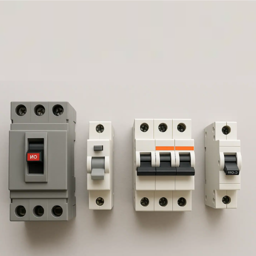
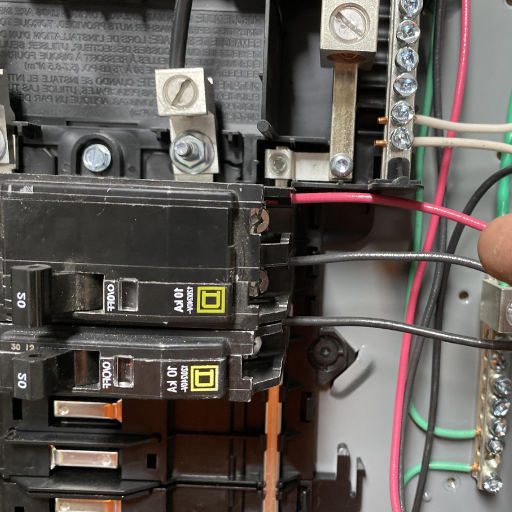
⚡ Circuit Breaker
A 30-amp double-pole circuit breaker is the standard circuit breaker used by electric dryers. The breaker generates 240-volt output power for the dryer machine by linking two 120-volt panels together.
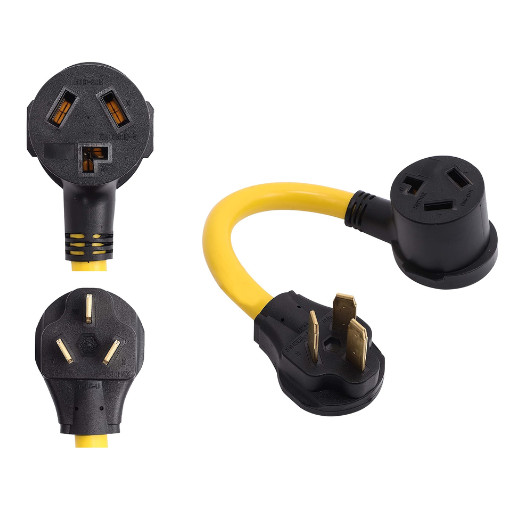
🔌 Older 3-Prong Systems
Some older homes may still utilize 3-prong outlets which include two hot wires and a neutral wire but lack a dedicated ground wire.
🔌 Modern 4-Prong Systems
Electrical codes currently require all new construction projects to install 4-prong outlets because these outlets provide an extra ground wire which improves user safety. The 4-wire system consists of two hots, one neutral, and one ground wire.
🔌 Outlet Type
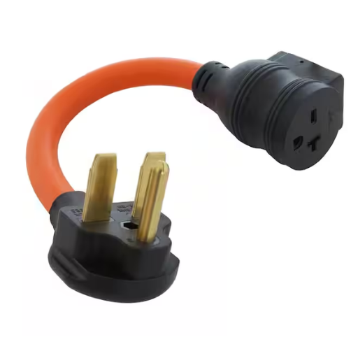
A NEMA 14-30R outlet serves as the preferred outlet for current installations whereas older homes used NEMA 10-30R outlets. The installation of a modern outlet and plug system needs to be completed because it helps to achieve safety compliance.
Practical Considerations
- ▶ Voltage and Power Demands: Electric dryers need 240 volts for their optimal operational performance. The models need between 4,000 and 6,000 watts of power which makes 30-amp circuits the safest way to handle their electrical requirements.
- ▶ Wire Length and Voltage Drop: Voltage drop becomes an important factor for installations that use longer wiring runs. The electrical panel needs an 8-gauge wire upgrade when the distance to the dryer exceeds 100 feet to maintain proper equipment operations.
- ▶ Compliance with NEC: The NEC requires all new electric dryer installations to use 4-prong outlets and circuits which provide maximal safety through their design that keeps ground and neutral connections separate.
Additional Tips
- ▶ You need to hire a licensed electrician to handle either your dryer circuit installation or your dryer circuit upgrade because this process requires professional expertise to avoid safety issues and equipment failures.
- ▶ You must perform inspections on dryer cords and outlets at regular intervals to check for any indications of deterioration or destruction.
- ▶ The use of an ENERGY STAR-certified dryer provides energy-efficient operation because it requires less electricity while maintaining its full operational capabilities.
Wiring for electric dryers should be done correctly because this practice enables safe device operation while reducing electrical hazards which include fires and short circuits. The current electrical standards need to be followed because they ensure both safe operations and dependable system functionality.
Wiring for RVs and Campers
The process of wiring RVs and campers requires experts to make careful plans which they need to follow through with established safety standards and reliable operations and energy-efficient results. RV electrical systems separate into two distinct systems which are the 12-volt DC system and the 120-volt AC system. The 12-volt DC system uses the RV battery to power essential operations which include lights water pumps and ventilation fans while the 120-volt AC system provides power to appliances that need external power sources which include air conditioners microwaves and TVs.
The correct wire gauge must be used when wiring RVs and campers because it protects the electrical system from dangerous overload conditions. According to the American Wire Gauge (AWG) standard a 15-amp circuit needs a minimum of 14-gauge wire while a 20-amp circuit needs 12-gauge wire. Using wires with inadequate gauge will cause overheating which leads to fire hazards.
The current RV wiring system has developed through new technology which allows solar power systems and lithium batteries to be implemented for improved energy independence. An RV can create renewable energy when its roof solar panels generate electricity. The standard 400-watt solar system generates 25-30 amps of electricity from direct sunlight during each hour which makes it appropriate for off-grid camping. The solar installation wiring process requires solar panels to connect with a charge controller which connects to batteries for efficient energy transmission while protecting battery functions.
The installation of circuit breakers and fuses which meet your RV system requirements will improve safety measures in your vehicle. All wet areas which include kitchens and bathrooms require the installation of Ground-Fault Circuit Interrupters (GFCIs) to protect against electrical shocks. The National Electric Code (NEC) requires all electrical installations to follow its established guidelines.
The correct electrical system installation for RVs and campers enables their electrical components to function properly while giving travelers confidence, which lasts from using campground shore power to operating with off-grid energy systems.
Wiring for Air Conditioning Units
The wiring for residential air conditioning systems needs to comply with specific standards which will ensure operational efficiency while protecting users from hazards and fulfilling electrical safety standards. The electricity requirements of modern air conditioning systems exceed typical household electrical capacity which needs dedicated electrical circuits for their operation. A central air conditioning system needs between 15 and 60 amps at 240 volts because its electrical demand depends on its specific size and cooling performance. Standard 120-volt circuits provide power to window and portable AC units which require between 7 to 20 amps of electrical current.
The electrical specifications of an air conditioning unit need to be verified before installation work begins. The unit displays this information through a label which shows the required details. The label includes details on voltage, current (in amps), and required breaker sizes. An appropriate circuit breaker and wiring system needs to be established to avoid equipment damage and fire hazards. For example, an air conditioning unit rated for 20 amps would typically require a 12-gauge wire at minimum.
According to the National Electric Code (NEC) proper grounding and an outdoor unit disconnect switch must be installed. The disconnect switch provides an additional safety feature which enables the unit to be turned off during maintenance and emergency situations. The installation of surge protection devices protects the unit from damage caused by power surges and lightning strikes through voltage spikes.
Homeowners select smart thermostats and variable-speed system controls for their installation because these devices provide energy savings while improving system efficiency. These systems frequently need 24-volt control wires which serve as extra low-voltage wiring for thermostat operations. Professional installation is essential for these complex setups because it ensures proper configuration and compliance with code requirements.
Always consult a licensed electrician to evaluate the wiring requirements based on your air conditioning unit’s specifications and your home’s electrical system capacity. The installation process establishes a secure and efficient system that operates effectively throughout its lifespan.
National Electrical Code (NEC) Standards for 30 Amp Circuits
The National Electrical Code (NEC) establishes complete regulations which ensure safety for both people and equipment when operating 30 amp circuits. The NEC requires a 10-gauge wire for 30 amp circuits because this wire size can carry the required current without overheating. The electrical system in homes uses these circuits to power large appliances which include air conditioners and electric water heaters and RVs.
📋 NEC Key Requirements
- ▶ The NEC requires 10 AWG copper conductors or 8 AWG aluminum conductors as wire requirements for 30 amp circuits to meet safety standards and system requirements.
- ▶ A 30 amp breaker must protect the 30 amp circuit from excessive current which creates a risk of overheating and fire hazards.
- ▶ NEC Article 210.19(A)(1) states that the circuit load should not exceed 80% of the circuit’s rating for continuous loads (running for 3 hours or more). The maximum load which a 30 amp circuit should carry during extended periods of operation stands at 24 amps.
- ▶ The NEC requires 30 amp circuits to use receptacles which have a 30 amp rating as their designated receptacle type.
- ▶ The NEMA 10-30 and NEMA TT-30 outlet configurations serve as the standard outlets for 30 amp circuits which depend on specific application needs.
- ▶ The NEC requires all circuit installations to have proper grounding. Grounding creates a protective barrier which prevents electrical shock to people during fault conditions. The grounding system must follow NEC Article 250 requirements.
Common Applications for 30 Amp Circuits
- ▶ HVAC Systems: Air conditioning units operate their required functions through 30 amp circuits which deliver necessary electrical power.
- ▶ Water Heaters: Electric water heaters typically require a dedicated 30 amp circuit.
- ▶ RV Hookups: Outdoor RV connections use 30 amp outlets which provide power to outdoor facilities.
Additional Notes: The process of wiring a 30 amp circuit requires consideration of wiring length and other essential elements. Excessive wire runs create voltage drops which necessitate wire size adjustments to maintain operational efficiency and regulatory standards. For example, wires longer than 100 feet may require upgrading to the next larger wire size. The planning and installation processes for a 30 amp circuit must follow both current NEC code updates and local building codes. The design and implementation process requires consultation with a licensed electrician to ensure compliance with safety standards.
Understanding NEC Guidelines for Wire Size
The National Electrical Code (NEC) provides complete instructional material which shows how to select the correct wire size by using current load and voltage and wire material and environmental factors as their basis. The correct wire size must be used in a 30-amp circuit because it protects against overheating and ensures safe operation and efficient performance. The NEC requires 10-gauge wire as the minimum wire size for 30-amp circuits because copper conductors must operate at 75 degrees Celsius. The wire size for aluminum conductors must be upgraded to 8-gauge because aluminum has lower conductivity than copper. The current-carrying capacity of wires establishes these standards which protect against overheating that creates fire hazards.
Ambient temperature and wire length require evaluation because these factors affect circuit performance. When the wire run exceeds 100 feet, you need to increase the wire size for voltage drop purposes. The distance electricity must travel creates voltage drop which reduces circuit efficiency and causes equipment to malfunction. The optimal performance standard requires performance voltage drop to remain below 3 percent. The recommended wire size for a 30-amp circuit which operates at 150 feet needs an upgrade to 8-gauge copper wire or larger.
The NEC calculates the required circuits based on different factors which include the wire insulation type which includes THHN and THWN and the total wire count inside the conduit and the permitted voltage drop limit. The installation of wires in high-temperature conditions or through conduit bundling requires temperature correction and adjustment factors because these conditions affect wire ampacity. Your wiring project requires you to follow both NEC standards and the specific local electrical codes which contain stricter requirements. The best method to achieve safety and compliance requirements involves hiring a licensed electrician for consultation.
Compliance with Safety Standards
Any electrical project requires strict adherence to safety regulations. The National Electrical Code (NEC) establishes complete safety requirements for electrical installations, but professionals must continually track new information and safety requirements to achieve their best protective results. The current NEC standards of upgrading systems to present power distribution equipment establishes a major safety improvement for power distribution equipment. The National Electrical Code (NEC) requires designers to select wire ampacity specifications according to two specific conditions. The NEC requires installers to apply ampacity correction factors for conductors starting from No. 10 size and above, when the temperature reaches 96°F or higher. The method enables conductors to maintain their performance capabilities, while their operational boundaries remain safeguarded.
The National Electrical Code (NEC) establishes minimum safety standards which local authorities can exceed through additional safety regulations that require more rigorous grounding requirements and circuit breaker specifications and insulation requirements. The local regulations need to be investigated and followed because they outline the necessary steps for achieving both legal compliance and safety requirements. The value of performing regular inspections should be treated as an essential aspect of building safety. Professional electrical inspections can identify hidden risks such as overloaded circuits, deteriorating wiring, or non-compliance with updated codes. The assessments become more precise through the use of modern equipment like thermal imaging technology, which generates specific data for developing corrective action plans. The combination of established code compliance with modern safety practices results in an electrical system that functions both securely and efficiently.
⚠️ Consequences of Non-Compliance
The violations will increase electrical fire hazards and damage equipment in addition to creating safety risks which might result in injuries or death. The company will suffer two types of consequences from non-compliance with regulations which include expensive fines and legal responsibilities and damage to its corporate reputation. The process of following safety rules delivers protection to both human beings and their possessions beyond its role as a legal requirement.
Visual Aids for Proper Wiring Techniques
The correct wiring techniques are required because they create safe electrical systems which function properly and comply with all applicable regulations. The following essential rules receive backing from visual materials and data which demonstrate their effectiveness.
- 1
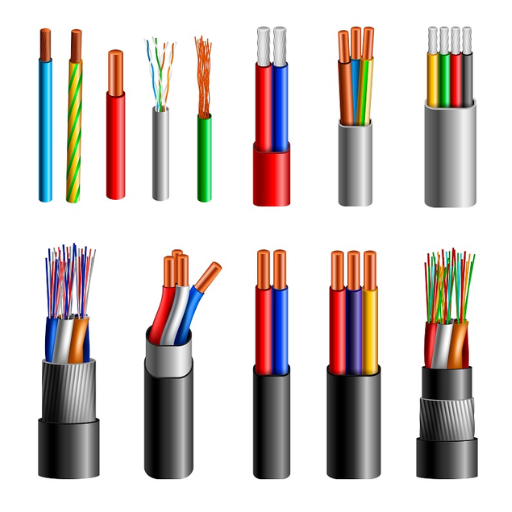
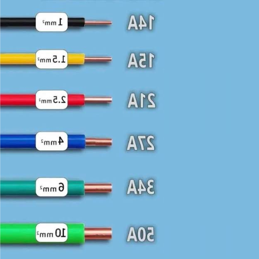
Color-Coded Wires
Purpose: The system makes it easy to identify three different types of wires which include live wires, neutral wires, and ground wires.
Standard Code Example: Black/Red wires function as live wires while White/Gray wires serve as neutral wires and Green/Bare Copper wires function as ground wires.
The National Electrical Code (NEC) states that following color codes results in a 25 percent decrease of wiring mistakes.
- 2
Secure Wire Connections
Technicians must use proper wire connectors like twist-on connectors to ensure secure connections without risk of disconnection. Technicians must verify that all wires connect properly to both outlets and switches.
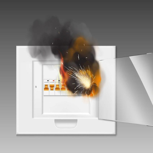
A report from Electrical Safety Foundation International (ESFI) found that loose connections are responsible for 14% of home electrical fires.
- 3
Prevent Overloading
Distribute loads evenly across circuits to avoid excess current. Use circuit breakers which have proper ratings according to their intended functions.
The main reason for electrical faults in homes occurs because circuits exceed their safe capacity which leads to approximately 50,000 residential fires each year in the United States.
- 4
Wire Stripping and Insulation Tips
The correct conductor length needs to be revealed through wire strippers. The technicians must treat the wire with caution because any wire damage will create broken connections and electrical shorts.
The study proves that properly stripped and insulated wires will extend their connection life by 40 percent.
- 5
Correct Cable Management Practices
The first step requires technicians to use cable ties and conduits for wire protection and organization of their system. The system needs to avoid creating sharp bends because this design leads to excessive tension.
The advantage of neatly routed cables results in 30 percent time savings for both repair work and troubleshooting activities. The techniques need to be executed with precision because they will enable systems to operate at their highest potential while eliminating dangerous situations that result from defective electrical systems. The implementation of best practices will achieve both ongoing reliability and safe operation of the system.
Note: Always adhere to local building codes and consult a licensed electrician for complex installations.
References
- Branch Circuit Breaker Selection & Wire Sizing — Guidelines for circuit breaker selection and allowable wire ampacities.
- Electric Wiring Chart — Wire size based on motor full load current and ampacity.
- National Electrical Code Allowable Ampacities of Insulated Conductors — Details on allowable ampacities for different wire sizes.