
Ground Fault Circuit Interrupters GFCIs serve an essential function in electrical safety because they protect homes and people from hazardous electrical faults. However, GFCI professionals need to learn about the two concepts called load and line because they must understand their differences. The distinction between these two elements needs to be understood because it serves as a foundation for installation procedures and troubleshooting methods and safety requirements in electrical systems. The article will explain how load and line GFCI connections function and describe their practical uses and handle load and line GFCI connections with confidence. This guide provides DIY enthusiasts and homeowners and experienced electricians with clear information that helps them use GFCIs safely and effectively.
Introduction to GFCI Outlets
What is a GFCI Outlet?
A Ground Fault Circuit Interrupter (GFCI) outlet functions as a safety device which helps protect people against electrical shock dangers that arise from ground faults. The system operates through continuous monitoring of electrical current which flows through a circuit. The GFCI system cuts off electrical power to the circuit when it detects an electrical current imbalance which typically occurs when electricity flows to a ground surface or water. The system provides immediate response which helps decrease both electrocution and injury hazards. GFCI outlets need installation in locations where bathrooms and kitchens and garages and outdoor areas experience water and electricity contact because these zones present potential danger situations.
Importance of GFCI in Electrical Safety
The implementation of Ground Fault Circuit Interrupters (GFCIs) as standard components in modern electrical systems has resulted in significant improvements to electrical safety because they provide protection against electrical hazards. GFCIs function by observing electricity movements to identify operational errors which usually occur when electrical current flows toward a grounded area. The GFCI system immediately stops electrical power when it detects any faults in order to safeguard against potential dangers. The research conducted on safety found that GFCIs effectively reduce fatal shock incidents which occur in damp environments because these areas have higher chances of electrical accidents.
Their deployment has become crucial in residential, commercial, and industrial settings, especially in areas like bathrooms, kitchens, basements, and outdoor outlets where electrical equipment is often exposed to moisture. GFCI technology has advanced through modern improvements which enhance both reliability and portability to create devices that users can easily control for multiple purposes. The implementation of these practices because they protect people from danger while creating safer ways to use electricity in our daily lives.
Overview of GFCI Outlet Wiring
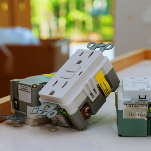
The correct installation of Ground Fault Circuit Interrupter (GFCI) outlets requires proper wiring to achieve electrical safety and meet regulatory standards. A GFCI outlet has both “line” and “load” terminals, which must be connected correctly to function as intended. The “line” terminals receive power supply from the electrical panel which serves the entire circuit. The load terminals of a circuit provide protection for all outlets that connect to the same circuit. The installation process of a GFCI outlet needs to begin with correct terminal identification which requires both secure connections and appropriate wiring materials.
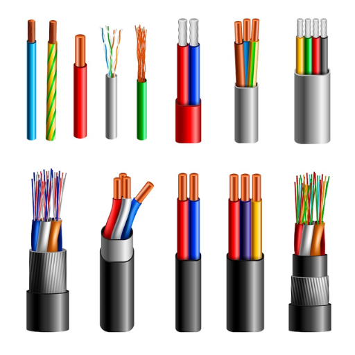
GFCI outlets need three-wire cable systems for their installation process which includes hot wire and neutral wire and ground wire. The hot wire connects to the brass terminal while the neutral wire connects to the silver terminal and the ground wire connects to the green or grounding terminal. The testing process requires checking the wiring system after installation because the outlet has built-in test and reset buttons which verify its operational status. The installation process needs to follow local electrical codes and guidelines to achieve both safety and long-lasting results. Modern GFCI outlets have evolved through design advancements which now include tamper resistance and LED indicators that enhance user experience and operational dependability.
Understanding Line vs Load Connections
Definition of Line and Load Terms
The terms “Line” and “Load” establish the fundamental framework which enables people to comprehend GFCI outlet operations within electrical circuits. The “Line” describes the collection of wires that deliver electrical power from the main electrical panel to the outlet. The wires function as the primary pathway which brings incoming electricity to the outlet, thereby guaranteeing its operational status. The “Load” establishes a connection which enables power distribution to all outlets and devices that the GFCI device safeguards. The installation process requires proper identification of these connections because the GFCI outlet will not work correctly when they get wired incorrectly. The design of contemporary GFCI outlets provides installation assistance through their “Line” and “Load” terminal designations which help prevent installation mistakes. The effective protection against electrical hazards depends on people understanding this distinction.
How Line and Load Connections Work
The “Line” connection in a GFCI outlet refers to the terminals where the incoming power from the main electrical panel is connected. The terminals provide electricity to the GFCI outlet which enables it to track electrical usage and safeguard the complete electrical system. The “Load” connection provides GFCI protection to all outlets and lights and devices which share the same circuit as the connection point.
The GFCI outlet needs correct wiring because it will monitor electrical current throughout the entire circuit. The system will shut down power whenever it finds an imbalance that causes current to travel through an unsafe path which includes water and human contact. The GFCI outlet will operate as a regular outlet when its Line and Load wires get installed incorrectly but it will lose all safety features which it should provide. The proper installation of wiring instructions together with post-installation testing needs to happen to achieve proper outlet function which will protect users and equipment from electrical dangers.
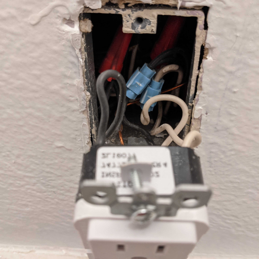
Identifying Line Wire and Load Wire
The correct identification of Line wire and Load wire during GFCI outlet installation requires technicians to understand both wire functions and their physical characteristics. The Line wire provides electrical power from the panel to the outlet through its connection with either brass or silver terminals. The Load wire connects to the terminal marked Load because it provides GFCI protection to all outlets located downstream from the GFCI outlet. The wires can be identified by their respective labels on the outlet or through testing which wire carries electricity using a voltage tester when the circuit operates. The following steps lead to correct wiring installation which results in safe operation and maximum performance.
GFCI Outlet Wiring Explained
Wiring a GFCI Outlet: Step-by-Step Guide
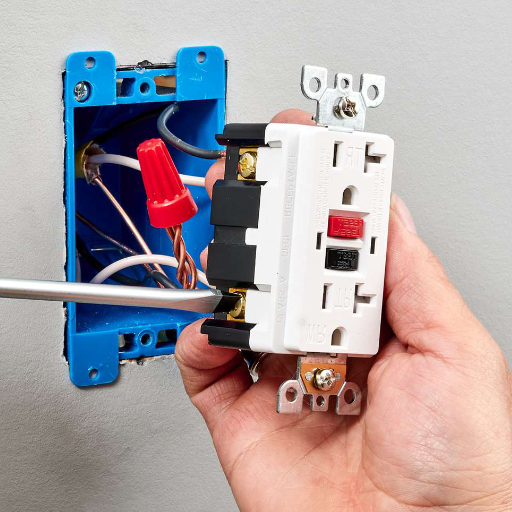
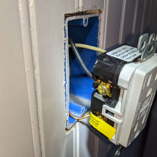
I use a systematic and safe method for wiring GFCI outlets because it helps me achieve both proper functionality and complete electrical code compliance. I begin the process by switching off power to the circuit at the breaker panel which I verify through testing with a non-contact voltage detector. The procedure establishes safety by eliminating all potential hazards that lead to electrical shock incidents.
Next, I identify the Line and Load wires. The Line wire delivers power from the panel to the outlet whereas the Load wire extends GFCI protection to other downstream outlets. I check for “Line” and “Load” labels on the back of the GFCI outlet to maintain clear understanding of the situation. I connect the Line wire to the terminals labeled “Line” which use gold or brass screws on the outlet; the connection requires that I attach hot (black) wire and neutral (white) wire to their matching terminals. I connect the wires leading to those outlets to the “Load” terminals when I use the Load terminals to protect additional outlets.
I proceed to insert wires into the electrical box while I install the GFCI outlet which I fasten with screws and finish by adding the faceplate. I press the reset button on the outlet before I restore power to check the outlet’s functionality through the built-in test and reset buttons. I use a GFCI outlet tester to check both wiring integrity and system operation to verify that everything functions properly. The outlet wiring process requires these specific steps to create a system which will provide secure and efficient operation for extended periods.
Common Wiring Mistakes to Avoid
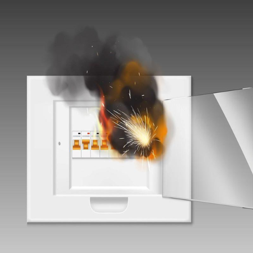
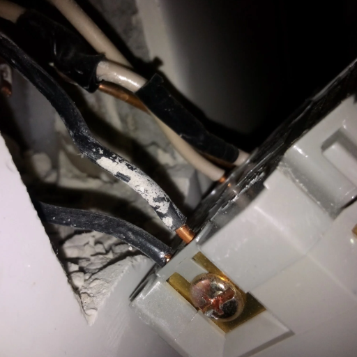
Multiple safety and equipment performance issues arise from installing GFCI outlets when technicians execute common errors during their work. One frequent error is reversing the line and load connections. This mistake prevents the GFCI from providing proper protection and can create a hazardous situation. The following problem occurs when the safety grounding wire remains unconnected which serves essential functions to protect people and secure the electrical system. The electrical boxes become dangerous when technicians exceed their capacity by installing excessive wiring which results in overheating and fire hazards. All wire connections need to be checked for security while technicians must remove any visible copper to prevent unintentional short circuits. The process requires two essential steps which involve wiring diagram analysis and following installation instructions plus checking all connections after each installation step.
Understanding Load Terminals and Line Terminals
The terms “load terminals” and “line terminals” are essential components of electrical wiring systems which include switches and outlets and circuit breakers. Line terminals serve as the connection points which link incoming power from the electrical source to the device. This is the side of the system which receives power directly from the electrical source that includes breaker panels. Load terminals function as the point which provides power to all devices that connect to their respective circuits. The device supplies power through its output to components which exist at multiple points throughout the circuit.
Correctly identifying these two terminals becomes essential because it enables safe and effective wiring procedures. The system will either malfunction or create safety risks when users connect the line and load terminals incorrectly. The GFCI (Ground Fault Circuit Interrupter) outlet becomes unsafe when users connect wires to incorrect terminals which results in safety features becoming nonfunctional. The process of working with load and line terminals requires three steps which involve following manufacturer instructions and installing wires with clear identification and testing electrical connections before power delivery starts to ensure safe operation and system performance.
Practical Applications of Load vs Line GFCI
Where to Use Load Connections
GFCI outlets have load connections which provide protection to all devices that users connect to their load terminals because the GFCI system will safeguard those devices against electrical hazards. This feature becomes essential because bathrooms and kitchens and outdoor areas must have safety measures for their multiple outlets which face risks from their damp environments. When you wire outlets in your garage or patio space, you should connect them to the GFCI load terminals because this will make all outlets stop working when ground faults happen, which improves your overall security. Users should limit their use of connections because they create challenges for troubleshooting and lead to equipment failures when used incorrectly. To achieve safe and effective installation results, users must follow manufacturer instructions and verify the intended use of their load circuit.
Benefits of Using Line Connections
The installation of GFCI systems through line connections provides an efficient solution which protects both single outlets and multiple circuits. The GFCI system achieves uninterrupted operation for non-protected areas because its line terminals serve as the only connection point which prevents any unintentional downstream device tripping. Line connections simplify both installation and maintenance because they require no extra wiring to downstream components which makes the system easier to handle. This approach improves diagnostic efficiency because GFCI tests show problems which exist only at the connected outlet or device and this process allows faster and more precise troubleshooting without affecting other outlets.
Real-World Scenarios and Examples
To demonstrate how GFCI technology functions, residential kitchens serve as an example of its practical use. The spaces contain several small kitchen appliances including blenders and coffee makers and toasters which people operate close to water sources that exist in sinks. GFCI outlets create a vital defense system which protects people from electrical shock dangers while they use their appliances. Outdoor locations such as gardens and patios which have installed lighting and power tools experience major advantages from GFCI system implementation especially during rainy weather conditions.
Another scenario exists at construction sites which serve as commercial facilities where unpredictable outdoor conditions expose electrical tools to danger. GFCIs protect workers by stopping ground faults from causing accidents during power tool operations in areas that have wet conditions or changing environmental factors. The GFCI design advancements of today have created devices which now provide better equipment protection and testing capabilities while maintaining their strong performance across various industry applications.
Conclusion and Best Practices
Associated As A Complete Circuit Of The Current
Ground Summing High-sensitivity Protection device (GFCI) are tenure mild hazarous circut breakers and they stop the electricity in case of their automobileshe persons cannot ot This is the biggest of all the difference because ppe are whole no about as nonsafe short com in pared to overload situations A key difference in the application of the GFCI is the use of low level high frequency model to quickly and easily detect areas of concern, such as moisture/ water infiltration in buildings and other electrical equipment installations. Nowadays, GFCIs are integrated with self-testing and other enhanced quality features due to the safety precautions and are designed to be low-cost which will suit a number of industrial applications. The use of GFCI has an certain order about it as it assists osha’s compliance regulations while helping to extend the safety function of protection to warehouses, office blocks as well as residences.
Recommended Practices for GFCI Installation
As far as I know, fitting Ground Fault Circuit Interrupters (GFCIs) has to be done strictly following the specific recommendations with a view to ensuring that all the goals are achieved. For beginners, the most vital point is to ascertain in which places GFCIs must be fitted – this may include mainly the kitchen, toilet, garage, the outgoing of small areas, such as ceil spaces, the utility room, the external connectivity points i.e., sockets etc. The safety-target GFCIs have safety locks that prevent electric shocks. This is why it is highly important to ensure that they are placed mostly in hazardous places.
In the process of installing a GFCI, the breaker controlling the circuit must be switched off to avoid electrical hazards. After locking out the breaker, the connection of the wiring goes as simple as following the labeling for the GFCI device. It is also standard to locate dual sets of terminals on the GFCI template, called “line” and “load.” The “line” refers to the incoming power from the electrical panel, whereas the “load” provides downstream protection if further devices are connected. I check very carefully if all the connections are made, because incorrect wiring of the device might cause improper operation or make the device unable to perform the protection functions correctly.
Having installed a GFCI, one of the measures I take is to test its functionality. A GFCI with an installed test button works in most cases and one can press this button to trip the power off and confirm that the system is working as intended. Then one can reset the system. This is really the most mechanical part for anyone who follows safety recommendations and would usually involve checking one’s pop-up GFCI outlets as often as it can be done in a given month to prevent untoward scenarios from misfiring too early. And so I keep these criteria in mind, knowing that the installer has secured at least a good level of installation and maintenance for the GFCIs.
Additional Study Materials
If you wish to build up your knowledge on the subject of the GFCI outlets and welfare in runs on electrical equipment, we would define a number of reliable sources of information. Websites with nationwide educational backgrounds including National Fire Protection Association (NFPA) and Consumer Product Safety Commission (CPSC) among some other give their rules and advice concerning safety while working with electricity and types of installation practice. Sometimes the manuals given by electricity providers answer the same questions particularly with reference to any particular region at issue. For practical cases which involve video preparation, it will be useful to find courses by specialists such as electricians. These materials stimulate the studying and accumulation of many correct-noterroneous facts instead of general instruction.
Reference Sources
-
Ground Fault Circuit Interrupters – University of Washington – Explains GFCI functionality, including its role in protecting against ground faults and overloads.
-
Electrical Safety Program – Appalachian State University – Details GFCI testing procedures and their role in cutting power to the load during faults.
-
Electrical Safety Guidelines – Georgia Institute of Technology – Provides insights into GFCI operation, focusing on its ability to interrupt circuits to the load during ground faults.
Frequently Asked Questions (FAQs)
Could you kindly explain the difference that you see between the terms ‘Line’ and ‘Load’ in the context of a GFCI?
Connected to the line terminal are the infeed cables from the distribution panel; the circuit is typically marked as LINE; these carry the load or line itself. The load terminal is feeding the other outlets further downstream as well as any other installations on the same circuit, meaning that the equipment connected to the outlet on the load side is also protected. The lines and loads simply extend the power to the next device on the line or turn on the power for protection. Wiring of line and load screws in the wrong way can leave the GFCI providing no gfci terrorism for the outlets downstream. Always switch off the circuit breaker and test with a voltage tester before touching the outlet box or wiring.
How can I connect a GFCI panel if I do not know which wire is what?
The incoming power from the teamline is also the line wire which wire must first be connected to the outlet; it generally has the black hot wire and the white neutral wire of which the black is the live or source wire. The black is called live because the white does not carry current; it is only connected to bottom of outlets in order for the current to return to the outlet only. Hence, the black which carries the current to the appliances is the live wire or source whereas the white one which returns or connects the current is the return or neutral wire. If you do want say the rest of the downstream outlets to be covered, then the cable that is loaded remains in the box. A non contact voltage tester can determine which wire is powered on in the line by checking incoming or rising voltage. If you don’t check the line input and kept it off, you may go beyond ground errors. This is why it is necessary to consult a qualified professional such as an electrician especially if you are not sure how to take it or decide what to do next and then the network other will also want a extension or there can be growth defined in the plan who is going to be in most need.
Will one GFCI protect all outlets on the circuit?
Yes, a single Present GFCI will guard sockets installed down flow to the GFCI outlet provided that the installation of the GFCI was done correctly and it was deliberately double wired so that a outlet is affected by the gfci downstream this is because the socket is protected by the gfci. If the outlets in this same circuit are connected to the -> load side of the GFCI then the outlets too wire and threre and will receive gfci protection. In the same manner as the above sentence, Any outlets in the same circuit which are connected to the -> load terminals will receive gfci protection and any outlets connected to the -> line side will not. To enable even more outlets to receive gfci protection, the steel components must be connected to the GFCI load terminals, while the line and load neutrals and hots connected. If the GFCI relays, it will take out all the loads on any that will be connected on the load side, so establish what exactly is fed from these outlets in case of any troubleshooting. A conscientious home owner should make sure the homes electrical installations are properly fixed to avoid future compromises on electrical safety.
Can you explain what happens if I accidentally interchange the line and load wires of my GFCI?
If you mistakenly connect your GFCI’s load wires (those installed after the outlet) to the line terminals (those connected to the source) and/or the incoming wires to its load terminals, you may put the receptacle into service, but not have it protected by the GFCI, or its downstream receptacles as well. Even if the GFCI will power the receptacle, putting the line on the GFCI which might be hot will make the GFCI useless. It may seem that the GFCI may switch on the device, but if measures of a voltage test appear relevant measures should be considered. A GFCI outlet usually comes with two sets of terminals and the line terminals are often very clearly visible. But there are instances where people get the wiring all mixed up within the outlet. A service person can easily determine line from load side and will wire line back to line. With the terminals in the right polarity there is no bonding and therefore functionality is resumed as per the electrical code.
Is there a simple way to check and see if the rest of the house structure is protected by the GFCI?
A ‘GFCI’ or ‘GLCI’ is either built into one of the wall receptacles, or can be a plug-in. Some of them are powered and come with a test button, in which case one can just check the reset button status of the GFCI box. If the reset button is still turned on then go and check the downstream outlets if they still have electricity. Should the outlets go off most particularly when the GFCI reset, the outlets are GFCI protected; and similar to the above if the orffushing occurs they are loads and are not in load the above outlets. By using the voltage tester every outlet can be checked for each cable’s hot, neutral and power supply. Ground wires, ground fault and other features should be checked lastly particularly if enabled on the tester. If the GFCI does not isolate its end user as required, verify that the line terminals do energize incoming supply, and grind the load and line terminals has been done properly.